Effects of Processing Conditions on Texture and Microstructure Evolution in Extra-Low Carbon Steel during Multi-Pass Asymmetric Rolling


 ,
,
Abstract
:
1. Introduction
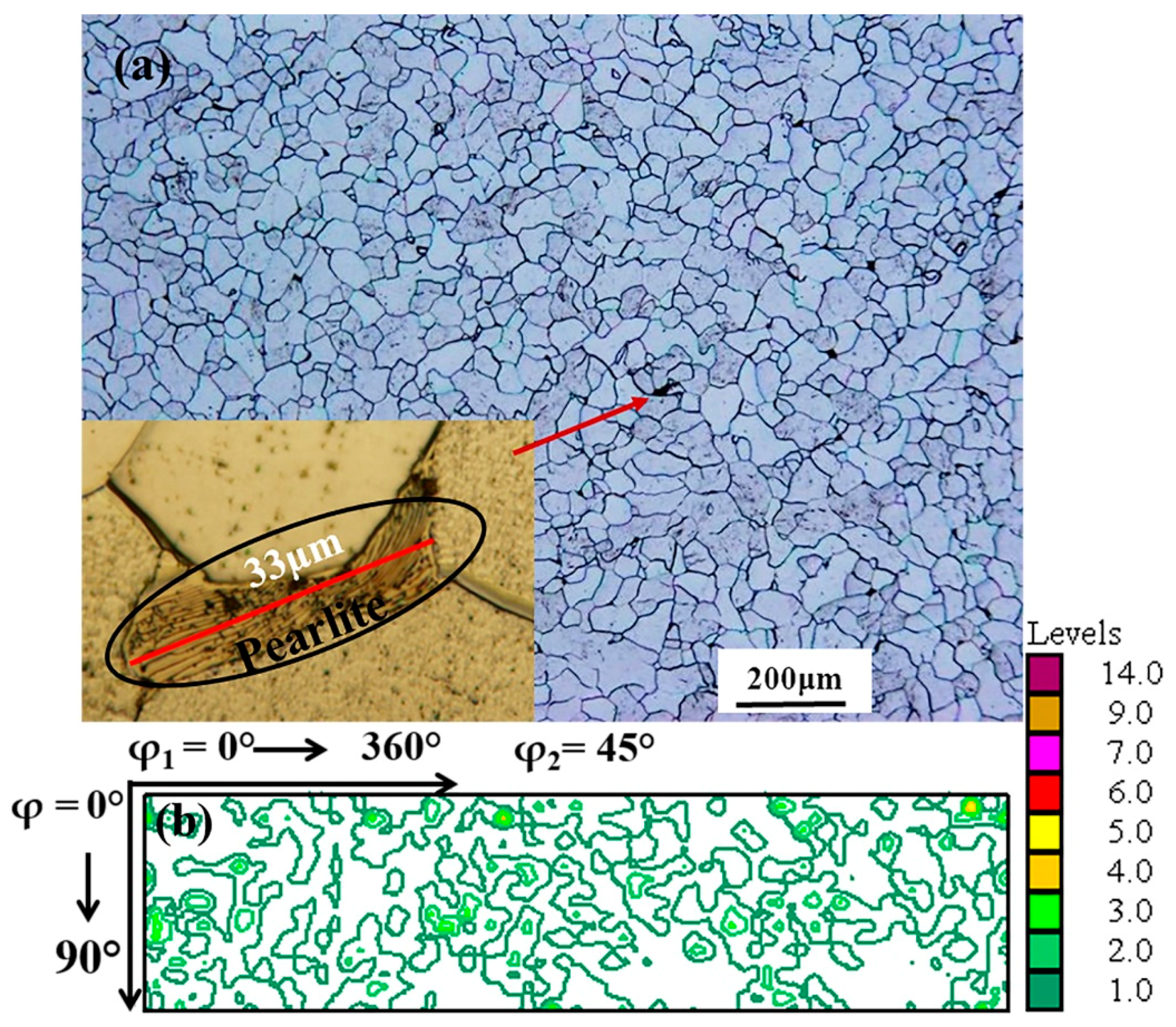
2. Materials and Methods
3. Results
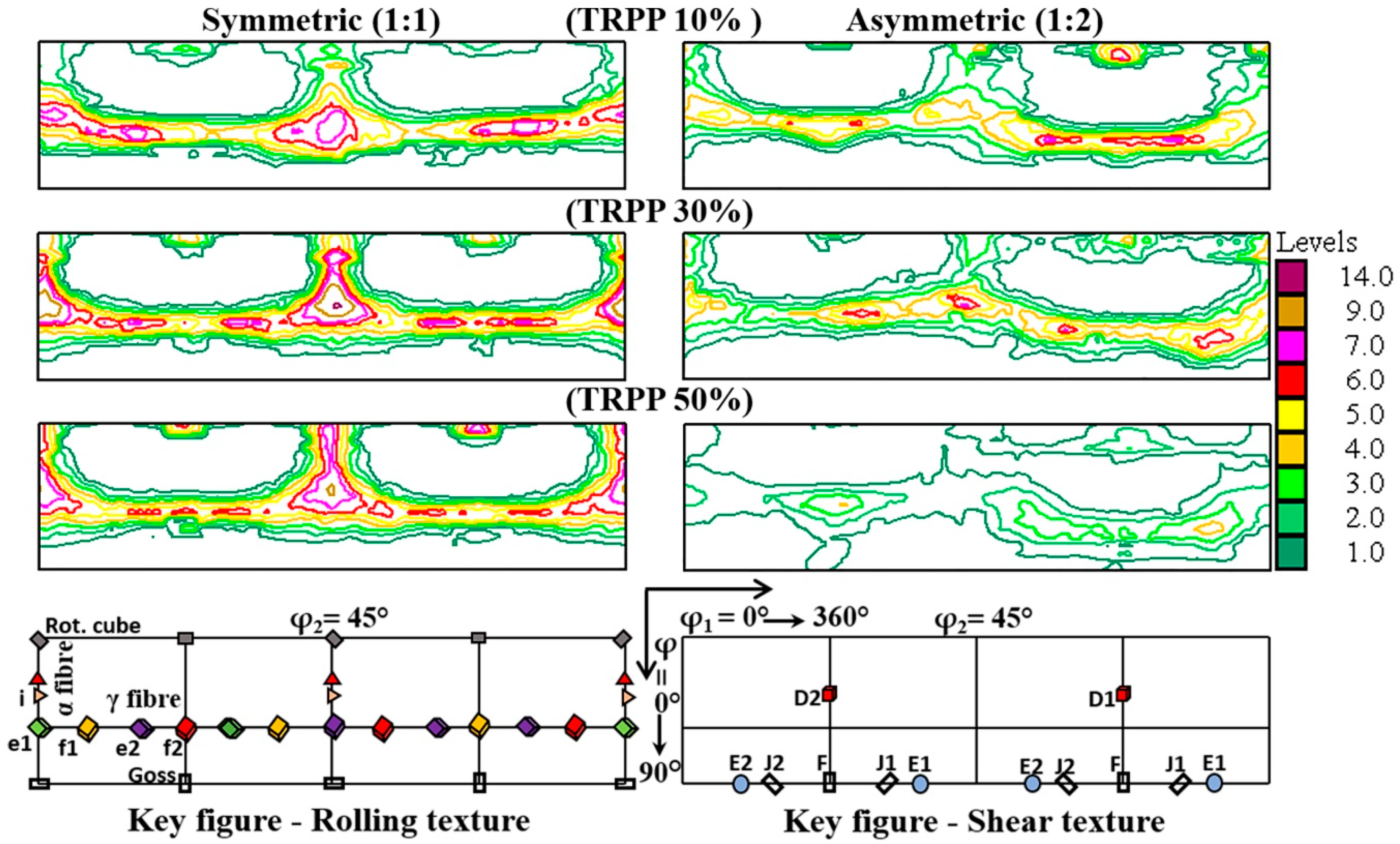
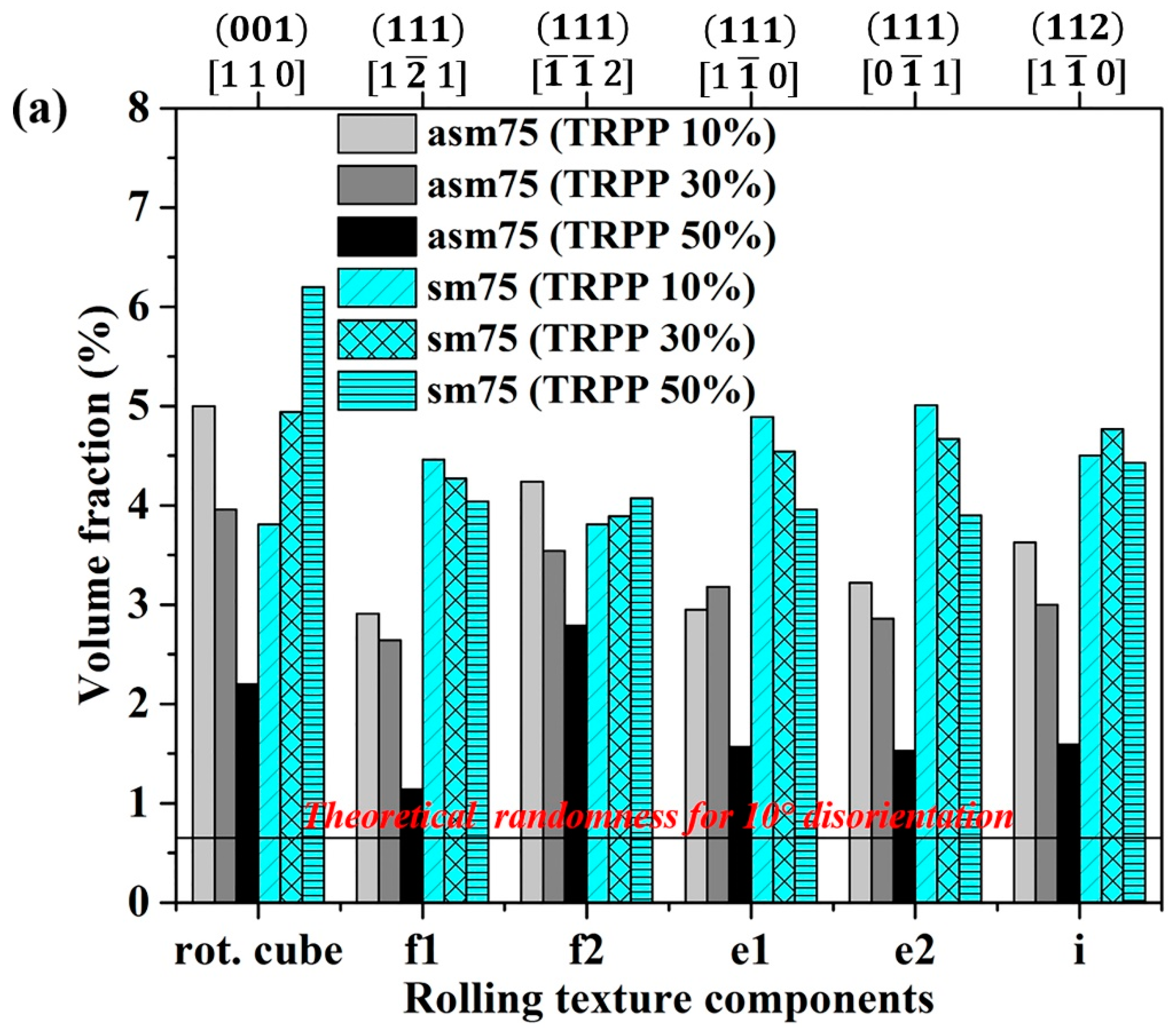
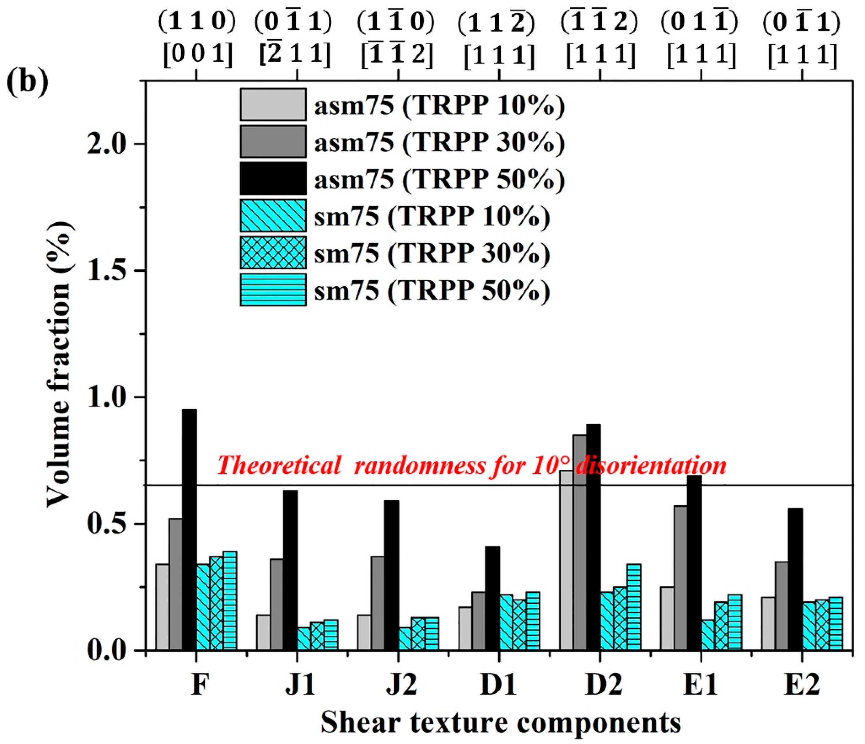
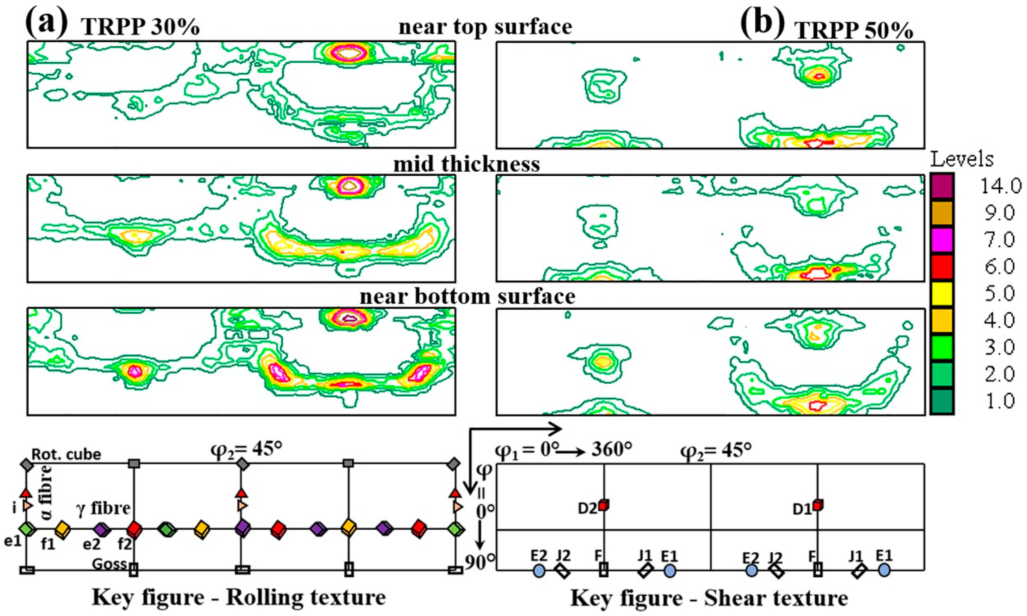
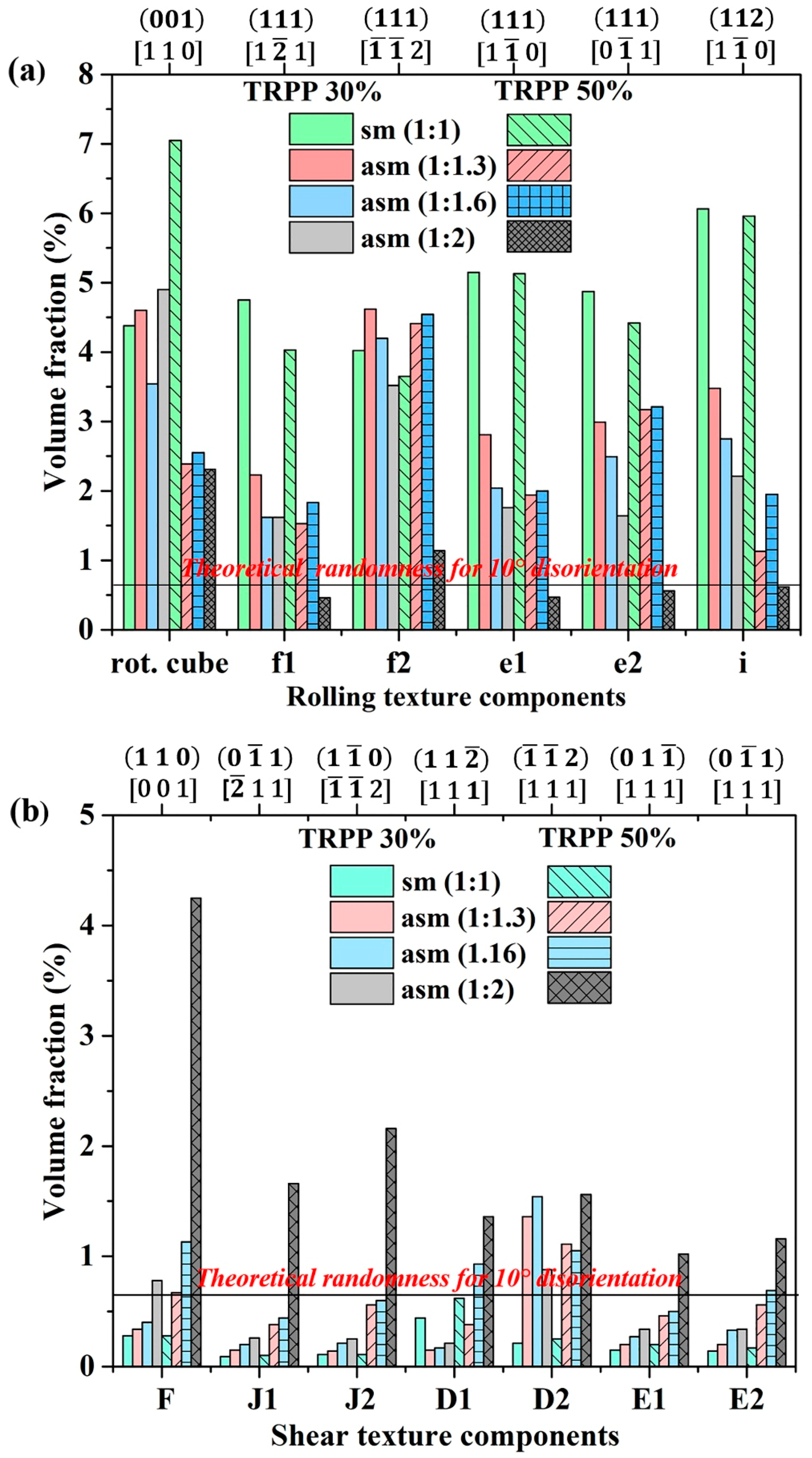
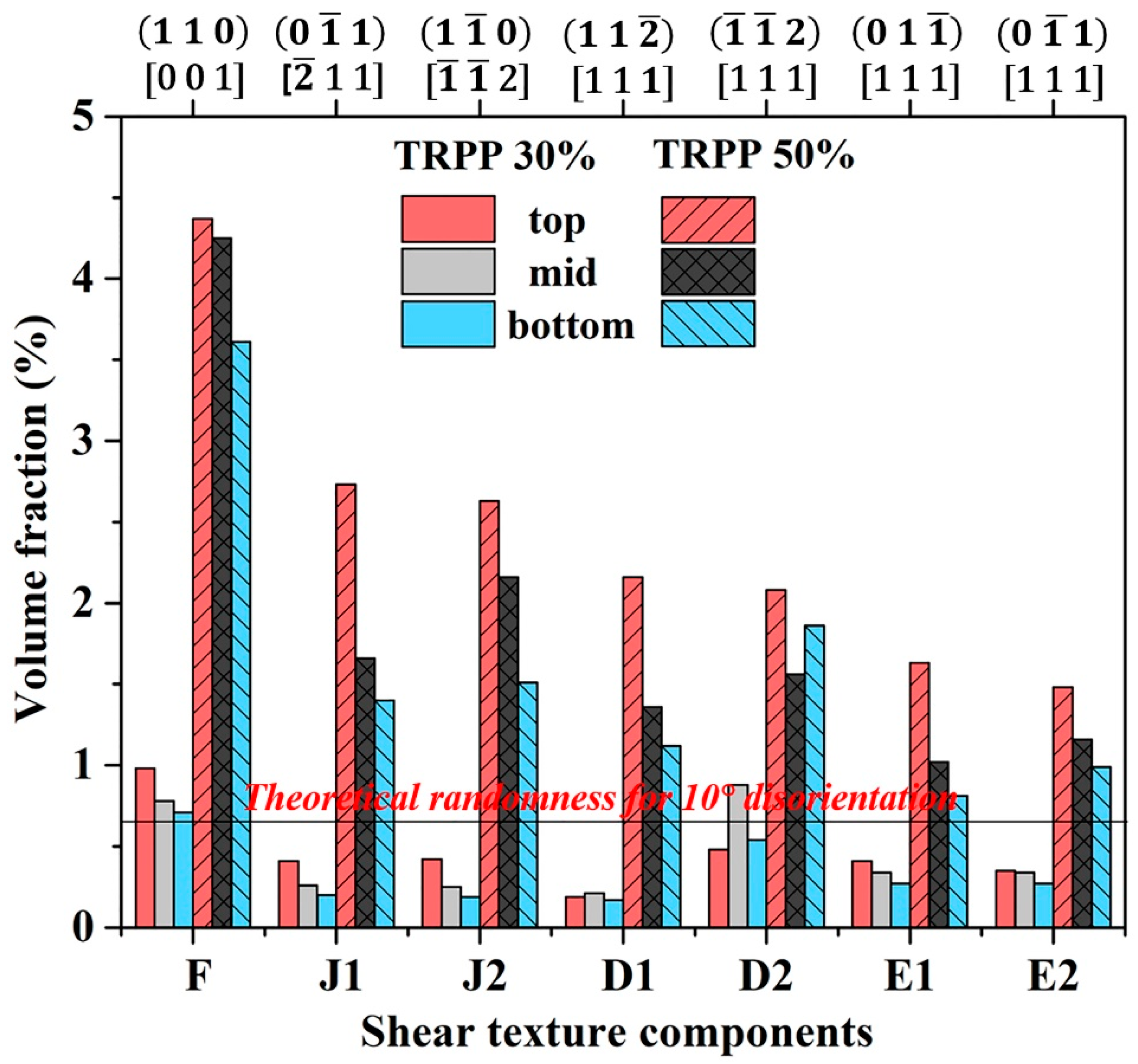
3.1. Texture
3.1.1. Medium Strain Range (75%)
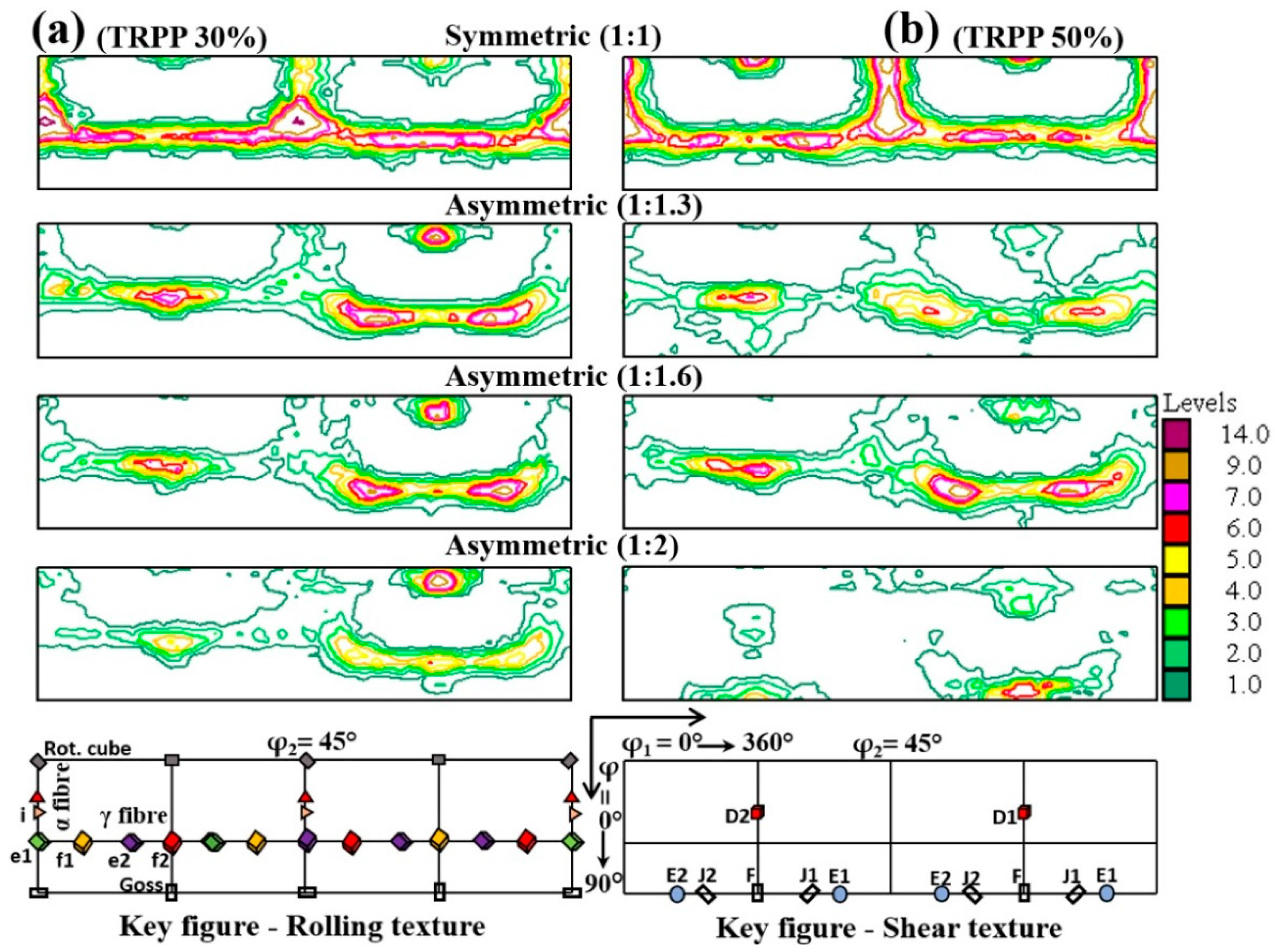
3.1.2. High Strain Range (89%)
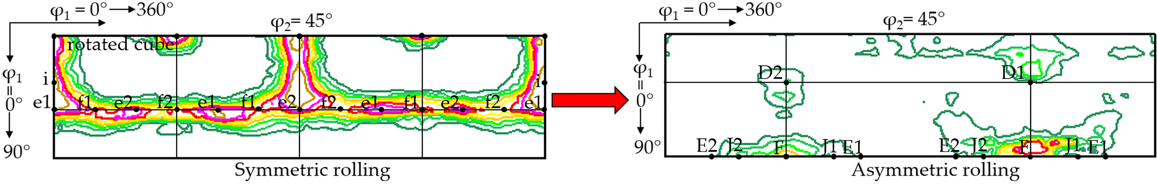
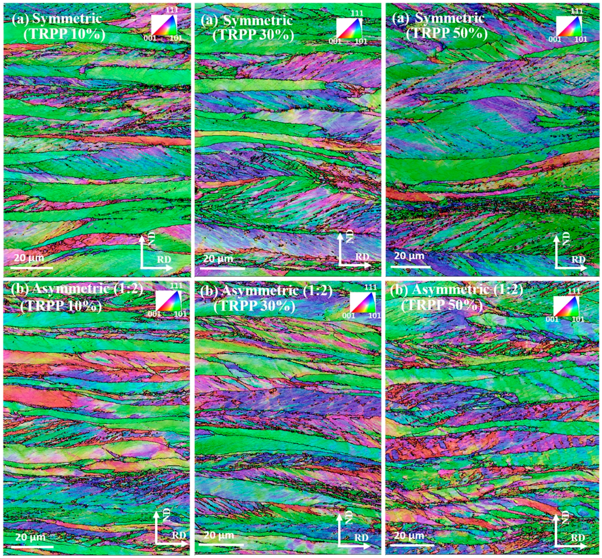
3.2. Microstructure
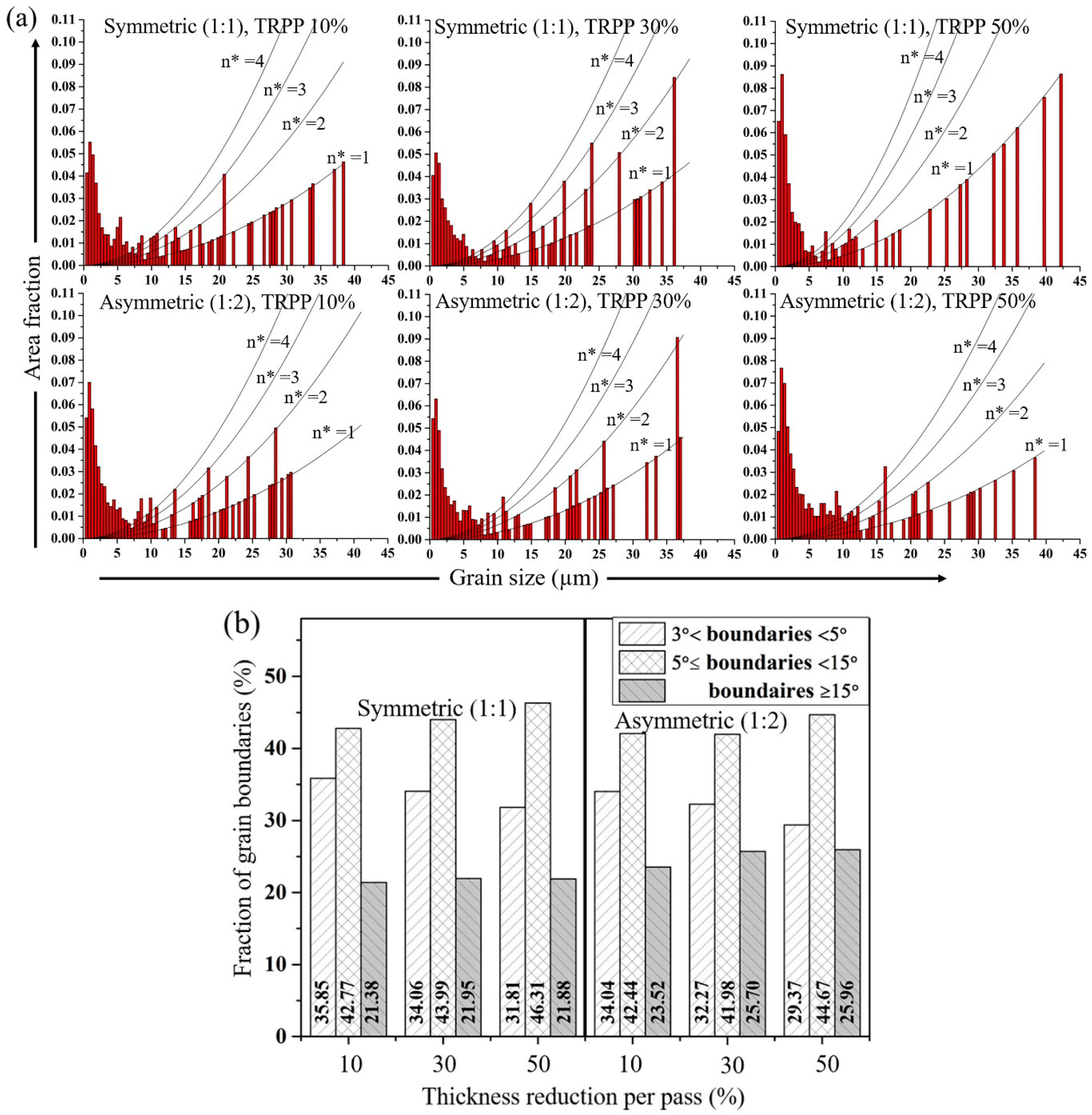
3.2.1. Medium Strain Range (75%)
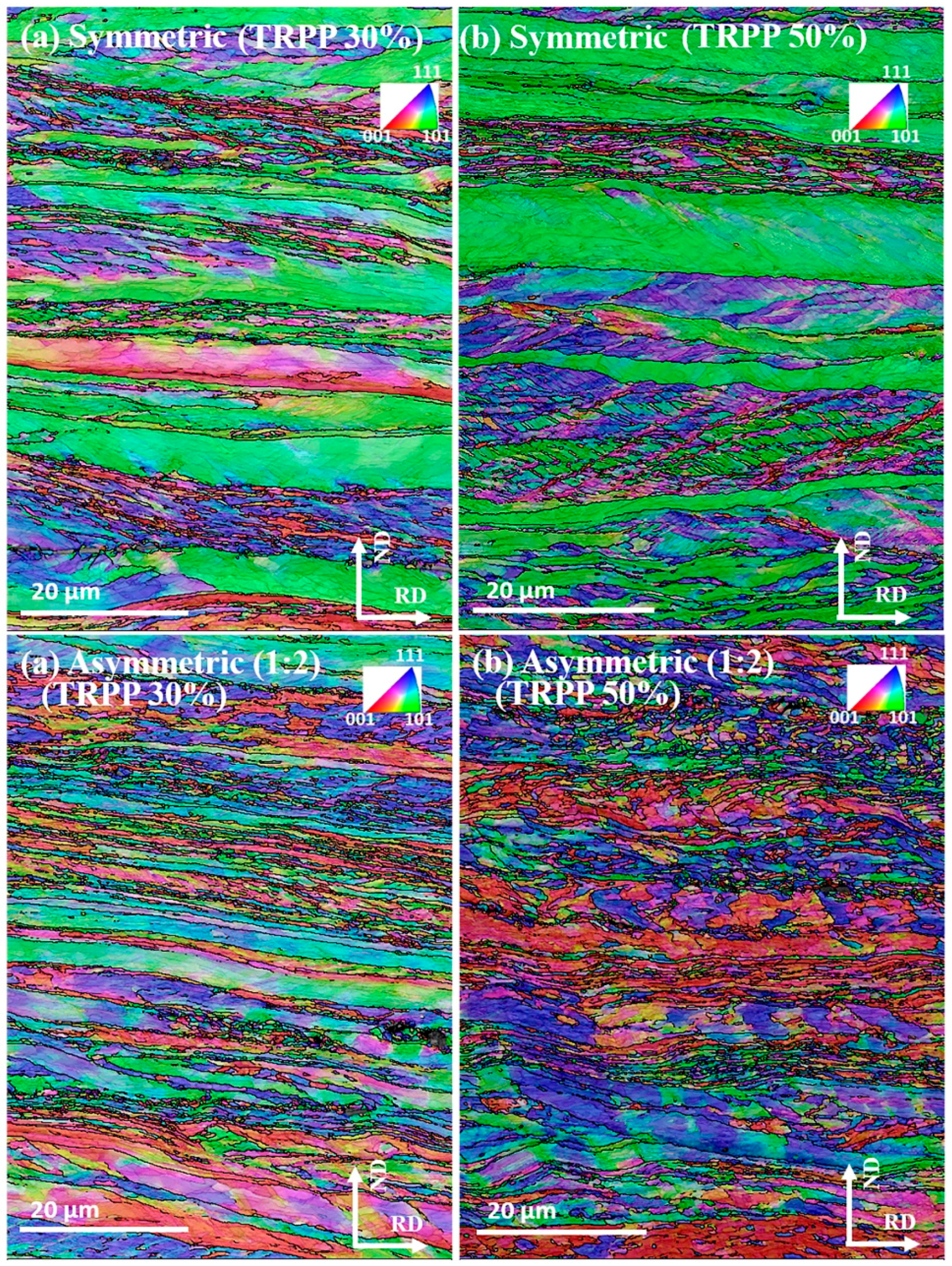
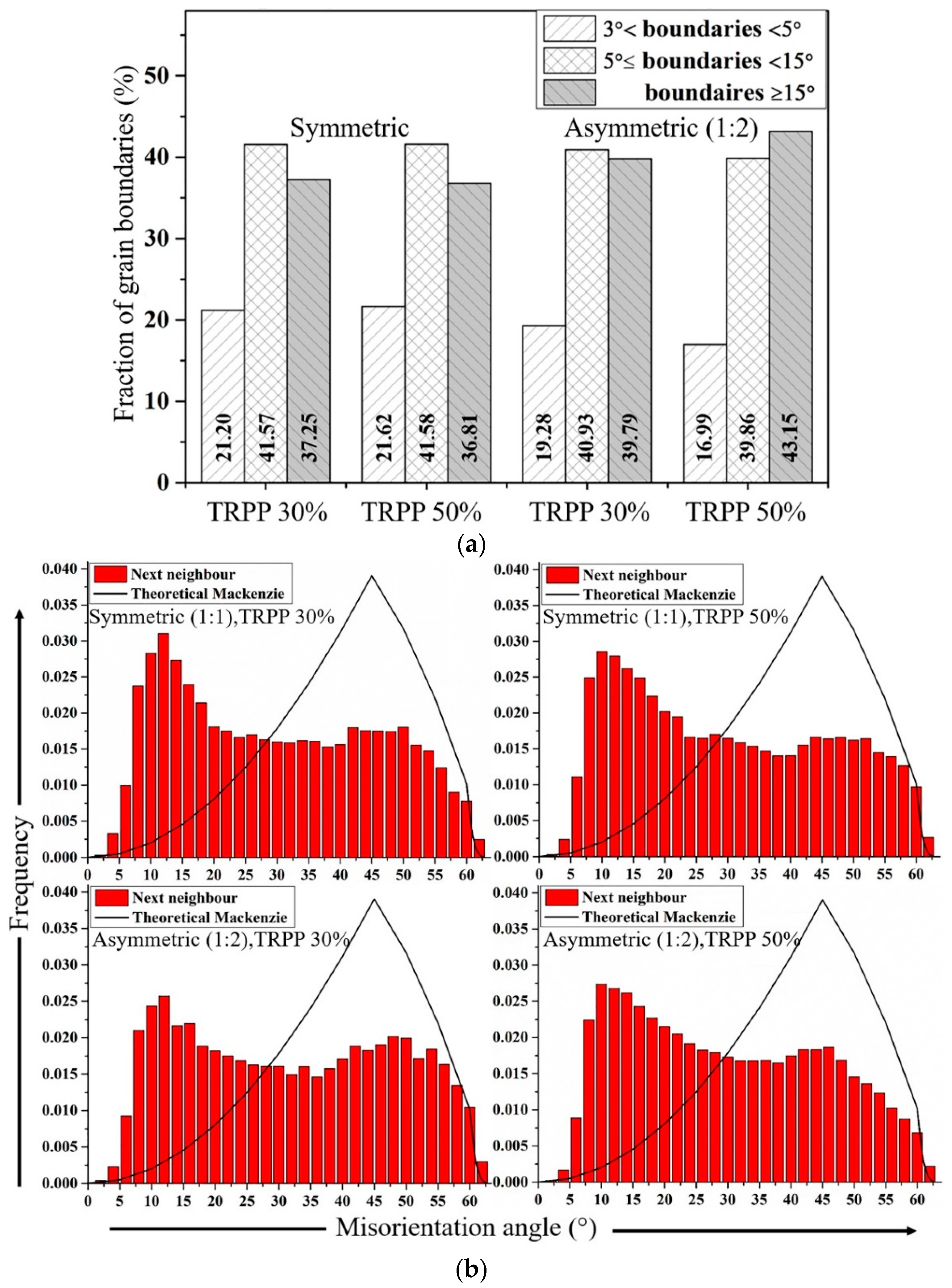
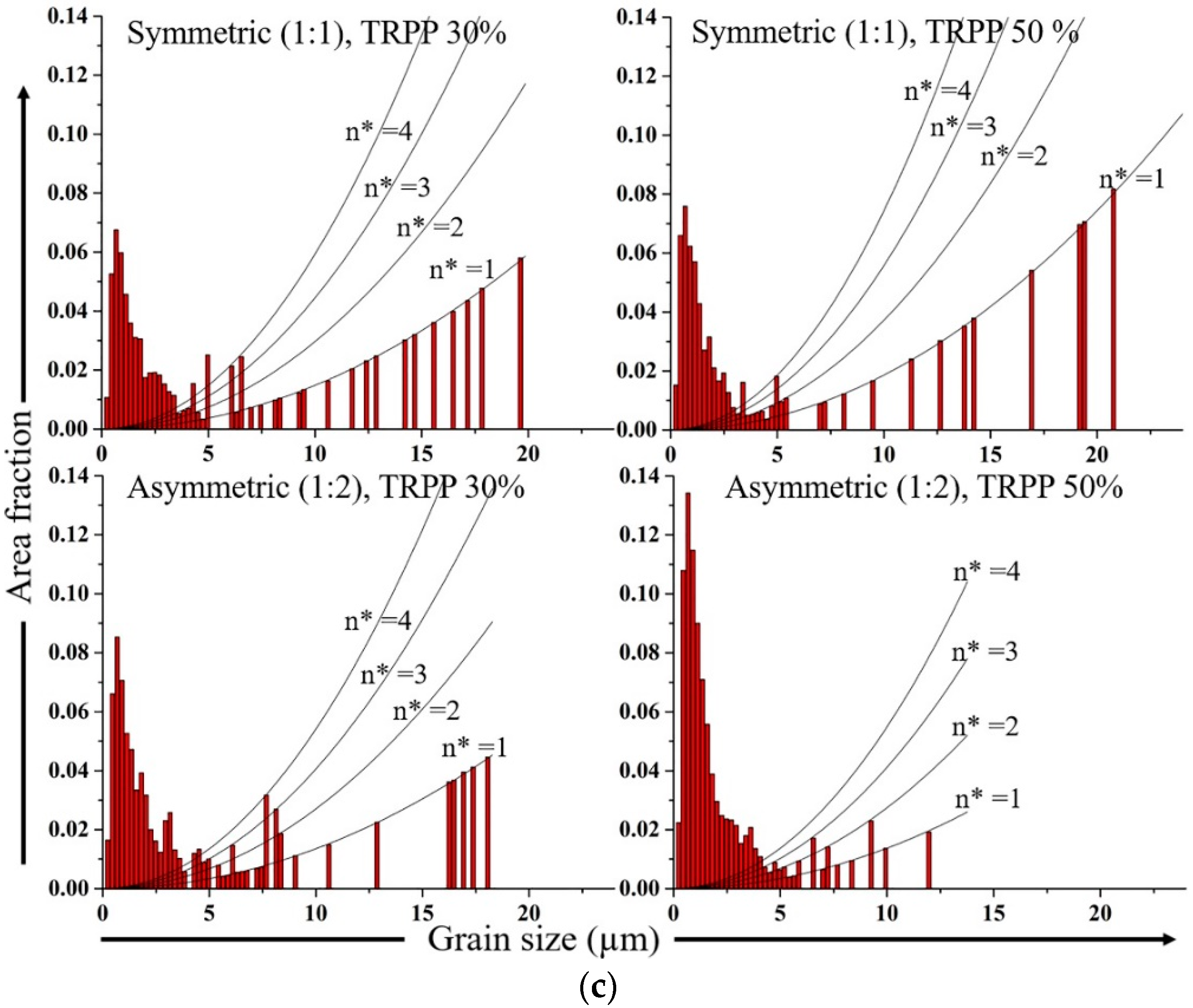
3.2.2. High Strain Range (89%)
4. Discussion
4.1. Texture
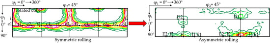
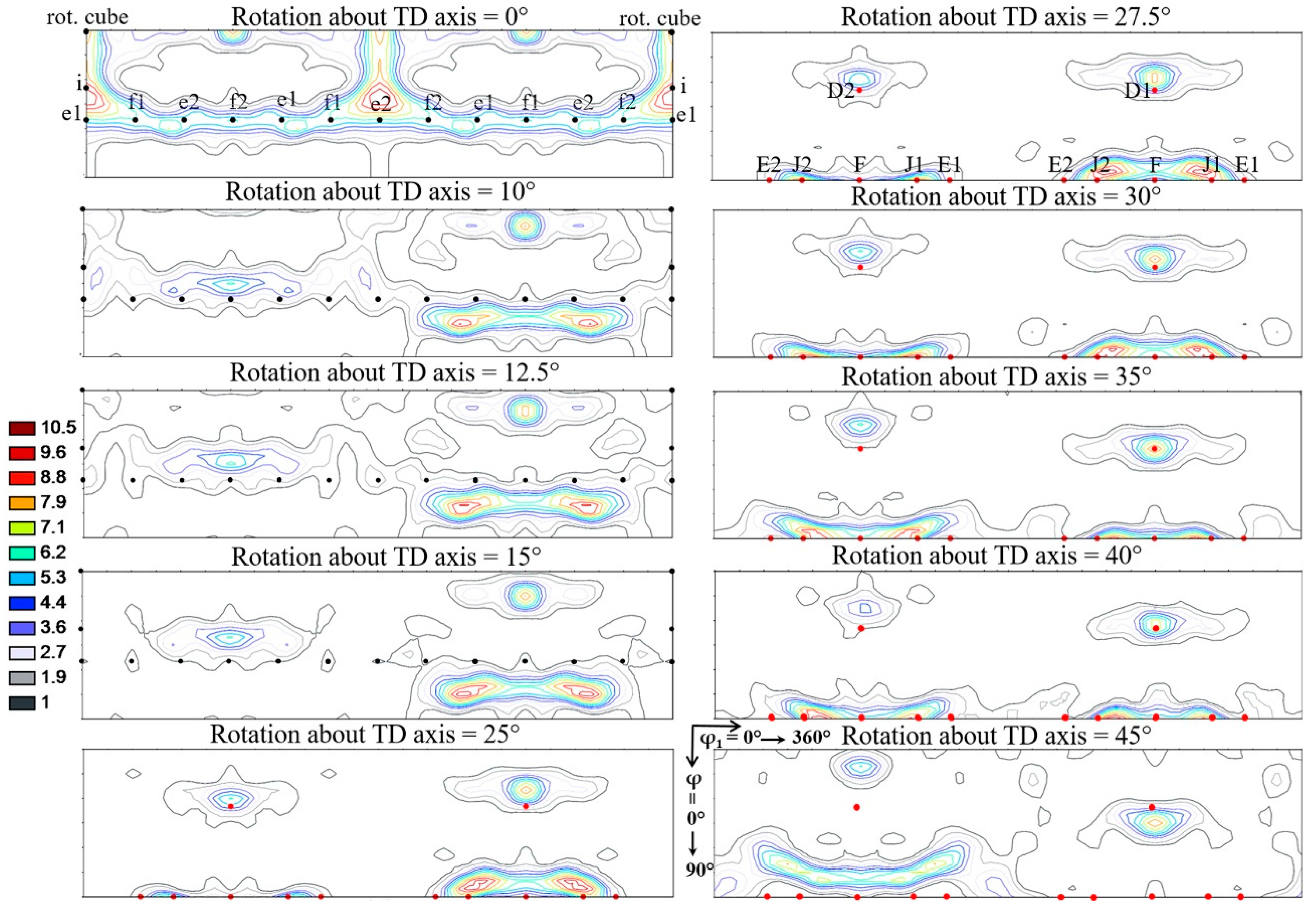
4.1.1. Relation between Rolling and Shear Textures
- The f1 and f2 rolling components are rotating exactly into the F component of the shear texture.
- The i rolling component produces the J1 and J2 shear components.
- The rotated cube produces both the D1 and D2 components of shear.
- The e1 and e2 rolling components are not rotating into any ideal shear component.
- The Goss rolling orientation does not need to be rotated to become stable orientation for shear; it is already the same orientation as the F shear component, so it remains stable for any imposed shear deformation after rolling.
4.1.2. Mixed Nature of the Textures Developing during Asymmetric Rolling
4.2. Microstructure
5. Conclusions
- 1
- The rotation of rolling texture towards the shear texture at the mid-thickness as well as its through-thickness homogeneity are significantly increased by the asymmetry-induced shear strain yielding from the applied TRPP and the final thickness reduction of the sheet with roll diameter ratios ≥1:1.6.
- 2
- For TRPP values below about 30%, the resultant texture of asymmetric rolling shows a greater similarity with the plane strain rolling texture compared to a conventional shear texture but prominent asymmetric trends exist in the preferred texture components especially in the f1 and f2 orientations ({111}<2>) of the rolling texture.
- 3
- The texture after asymmetric rolling (1:2) resembles to an ideal shear texture when the deformation is extended to the high strain regime and for high TRPP such as 50%.
- 4
- It has been shown that an approximately 35° rigid body rotation of the rolling texture around the TD axis transforms a typical symmetric rolling texture into a shear texture. Form this, it has been estimated that the shear component generated by the asymmetry conditions has to be at least 1.2 in order to get a shear texture.
- 5
- The shear texture that can be obtained by asymmetric rolling inherits several texture components from the symmetric rolling texture. A list of them is provided in this study.
- 6
- Asymmetric rolling is advantageous for grain refinement and for the creation of deformation induced HAGBs as compared to symmetric rolling under similar conditions. However, the significance of this advantage depends primarily on the final total thickness reduction and is associated with the degree of rotation of the rolling texture.
Author Contributions
Funding
Acknowledgments
Conflicts of Interest
References
- Saito, Y.; Utsunomiya, H.; Tsuji, N.; Sakai, T. Novel ultra-high straining process for bulk materials—Development of the accumulative roll-bonding (ARB) process. Acta Mater. 1999, 47, 579–583. [Google Scholar] [CrossRef]
- Segal, V.M. Equal channel angular extrusion: From macromechanics to structure formation. Mater. Sci. Eng. A 1999, 271, 322–333. [Google Scholar] [CrossRef]
- Tsuji, N.; Saito, Y.; Lee, S.H.; Minamino, Y. ARB (Accumulative Roll-Bonding) and other new techniques to produce bulk ultrafine grained materials. Adv. Eng. Mater. 2003, 5, 338–344. [Google Scholar] [CrossRef]
- Valiev, R.Z.; Zehetbauer, M.J.; Estrin, Y.; Höppel, H.W.; Ivanisenko, Y.; Hahn, H.; Wilde, G.; Roven, H.J.; Sauvage, X.; Langdon, T.G. The innovation potential of bulk nanostructured materials. Adv. Eng. Mater. 2007, 9, 527–533. [Google Scholar] [CrossRef]
- Tóth, L.S.; Lapovok, R.; Hasani, A.; Gu, C. Non-equal channel angular pressing of aluminum alloy. Scr. Mater. 2009, 61, 1121–1124. [Google Scholar] [CrossRef]
- Efe, M.; Moscoso, W.; Trumble, K.P.; Dale Compton, W.; Chandrasekar, S. Mechanics of large strain extrusion machining and application to deformation processing of magnesium alloys. Acta Mater. 2012, 60, 2031–2042. [Google Scholar] [CrossRef]
- Sagapuram, D.; Efe, M.; Moscoso, W.; Chandrasekar, S.; Trumble, K.P. Controlling texture in magnesium alloy sheet by shear-based deformation processing. Acta Mater. 2013, 61, 6843–6856. [Google Scholar] [CrossRef]
- Lapovok, R.; Tóth, L.S.; Winkler, M.; Semiatin, S.L. A comparison of continuous SPD processes for improving the mechanical properties of aluminum alloy 6111. J. Mater. Res. 2009, 24, 459–469. [Google Scholar] [CrossRef] [Green Version]
- Beausir, B.; Biswas, S.; Kim, D.I.; Tóth, L.S.; Suwas, S. Analysis of microstructure and texture evolution in pure magnesium during symmetric and asymmetric rolling. Acta Mater. 2009, 57, 5061–5077. [Google Scholar] [CrossRef]
- Sidor, J.; Miroux, A.; Petrov, R.; Kestens, L. Microstructural and crystallographic aspects of conventional and asymmetric rolling processes. Acta Mater. 2008, 56, 2495–2507. [Google Scholar] [CrossRef]
- Sakai, T.; Hamada, S.; Saito, Y. Improvement of the r-value in 5052 aluminum alloy sheets having through-thickness shear texture by 2-pass single-roll drive unidirectional shear rolling. Scr. Mater. 2001, 44, 2569–2573. [Google Scholar] [CrossRef]
- Utsunomiya, H.; Ueno, T.; Sakai, T. Improvement in the r-value of aluminum sheets by differential-friction rolling. Scr. Mater. 2007, 57, 1109–1112. [Google Scholar] [CrossRef]
- Huang, X.; Suzuki, K.; Chino, Y. Improvement of stretch formability of pure titanium sheet by differential speed rolling. Scr. Mater. 2010, 63, 473–476. [Google Scholar] [CrossRef]
- Kim, H.-K.; Kim, H.-W.; Cho, J.-H.; Lee, J.-C. High-formability Al alloy sheet produced by asymmetric rolling of strip-cast sheet. Mater. Sci. Eng. A 2013, 574, 31–36. [Google Scholar] [CrossRef]
- Kim, K.H.; Lee, D.N. Analysis of deformation textures of asymmetrically rolled aluminum sheets. Acta Mater. 2001, 49, 2583–2595. [Google Scholar] [CrossRef]
- Lee, S.H.; Lee, D.N. Analysis of deformation textures of asymmetrically rolled steel sheets. Int. J. Mech. Sci. 2001, 43, 1997–2015. [Google Scholar] [CrossRef]
- Jin, H.; Lloyd, D.J. Evolution of texture in AA6111 aluminum alloy after asymmetric rolling with various velocity ratios between top and bottom rolls. Mater. Sci. Eng. A 2007, 465, 267–273. [Google Scholar] [CrossRef]
- Huang, X.; Suzuki, K.; Watazu, A.; Shigematsu, I.; Saito, N. Effects of thickness reduction per pass on microstructure and texture of Mg–3Al–1Zn alloy sheet processed by differential speed rolling. Scr. Mater. 2009, 60, 964–967. [Google Scholar] [CrossRef]
- Roumina, R.; Sinclair, C.W. Deformation geometry and through-thickness strain gradients in asymmetric rolling. Metall. Mater. Trans. A 2008, 39, 2495–2503. [Google Scholar] [CrossRef]
- Polkowski, W.; Jóźwik, P.; Polański, M.; Bojar, Z. Microstructure and texture evolution of copper processed by differential speed rolling with various speed asymmetry coefficient. Mater. Sci. Eng. A 2013, 564, 289–297. [Google Scholar] [CrossRef]
- Orlov, D.; Pougis, A.; Lapovok, R.; Toth, L.; Timokhina, I.; Hodgson, P.; Haldar, A.; Bhattacharjee, D. Asymmetric rolling of interstitial-free steel using differential roll diameters. Part I: Mechanical properties and deformation textures. Metall. Mater. Trans. A 2013, 44, 4346–4359. [Google Scholar] [CrossRef]
- Tóth, L.S.; Beausir, B.; Orlov, D.; Lapovok, R.; Haldar, A. Analysis of texture and R value variations in asymmetric rolling of IF steel. J. Mater. Process. Technol. 2012, 212, 509–515. [Google Scholar] [CrossRef]
- Kim, W.J.; Lee, B.H.; Lee, J.B.; Lee, M.J.; Park, Y.B. Synthesis of high-strain-rate superplastic magnesium alloy sheets using a high-ratio differential speed rolling technique. Scr. Mater. 2010, 63, 772–775. [Google Scholar] [CrossRef]
- Kim, W.J.; Yoo, S.J.; Lee, J.B. Microstructure and mechanical properties of pure Ti processed by high-ratio differential speed rolling at room temperature. Scr. Mater. 2010, 62, 451–454. [Google Scholar] [CrossRef]
- Kim, W.J.; Lee, Y.G.; Lee, M.J.; Wang, J.Y.; Park, Y.B. Exceptionally high strength in Mg–3Al–1Zn alloy processed by high-ratio differential speed rolling. Scr. Mater. 2011, 65, 1105–1108. [Google Scholar] [CrossRef]
- Choi, C.H.; Kim, K.; Lee, D.N. The effect of shear texture development on the formability in rolled aluminum alloys sheets. Mater. Sci. Forum 1998, 273–275, 391–396. [Google Scholar] [CrossRef]
- Jeong, H.; Park, S.; Ha, T. Evolution of shear texture according to shear strain ratio in rolled FCC metal sheets. Met. Mater. Int. 2006, 12, 21–26. [Google Scholar] [CrossRef]
- Lapovok, R.; Orlov, D.; Timokhina, I.B.; Pougis, A.; Toth, L.S.; Hodgson, P.D.; Haldar, A.; Bhattacharjee, D. Asymmetric rolling of interstitial-free steel using one idle roll. Metall. Mater. Trans. A 2012, 43, 1328–1340. [Google Scholar] [CrossRef]
- Nguyen Minh, T.; Sidor, J.J.; Petrov, R.H.; Kestens, L.A. Texture evolution during asymmetrical warm rolling and subsequent annealing of electrical steel. Mater. Sci. Forum 2012, 702–703, 758–761. [Google Scholar] [CrossRef]
- Truszkowski, W.; Krόl, J.; Major, B. Inhomogeneity of rolling texture in fcc metals. MTA 1980, 11, 749–758. [Google Scholar] [CrossRef]
- Truszkowski, W.; Krόl, J.; Major, B. On penetration of shear texture into the rolled aluminum and copper. MTA 1982, 13, 665–669. [Google Scholar] [CrossRef]
- Sakai, T.; Saito, Y.; Kato, K. Texture formation in low carbon Ti bearing steel sheets by high speed hot rolling in ferrite region. Trans. Iron Steel Inst. Jpn. 1988, 28, 1036–1042. [Google Scholar] [CrossRef]
- Mishin, O.V.; Bay, B.; Jensen, D.J. Through-thickness texture gradients in cold-rolled aluminum. Metall. Mater. Trans. A 2000, 31, 1653–1662. [Google Scholar] [CrossRef]
- Beausir, B.; Fundenberger, J.J. ATOM-Analysis Tool for Orientation Maps. Available online: http://www.atex-software.eu/ (accessed on 26 July 2018).
- Toth, L.S.; Biswas, S.; Gu, C.; Beausir, B. Notes on representing grain size distributions obtained by electron backscatter diffraction. Mater. Char. 2013, 84, 67–71. [Google Scholar] [CrossRef]
- Dillamore, I.L.; Roberts, J.G.; Bush, A.C. Occurrence of shear bands in heavily rolled cubic metals. Met. Sci. 1979, 13, 73–77. [Google Scholar] [CrossRef]
- Chen, Q.Z.; Quadir, M.Z.; Duggan, B.J. Shear band formation in IF steel during cold rolling at medium reduction levels. Philos. Mag. 2006, 86, 3633–3646. [Google Scholar] [CrossRef]
- Yeung, W.Y.; Duggan, B.J. Shear band angles in rolled F.C.C. materials. Acta Metall. 1987, 35, 541–548. [Google Scholar] [CrossRef]
- Mishra, S.; Därmann, C.; Lücke, K. On the development of the goss texture in iron-3% silicon. Acta Metall. 1984, 32, 2185–2201. [Google Scholar] [CrossRef]
- Shimizu, Y.; Ito, Y.; Iida, Y. Formation of the Goss orientation near the surface of 3 pct silicon steel during hot rolling. MTA 1986, 17, 1323–1334. [Google Scholar] [CrossRef]
- Wonsiewicz, B.C.; Chin, G.Y. Inhomogeneity of plastic flow in constrained deformation. Metall. Trans. 1970, 1, 57–61. [Google Scholar]
- Baczynski, J.; Jonas, J.J. Texture development during the torsion testing of α-iron and two IF steels. Acta Mater. 1996, 44, 4273–4288. [Google Scholar] [CrossRef]
- Böcker, A.; Klein, H.; Bunge, H. Development of cross-rolling textures in Armco-iron. Texture Microstruct. 1990, 12, 103–123. [Google Scholar] [CrossRef]
- Nguyen-Minh, T.; Sidor, J.J.; Petrov, R.H.; Kestens, L.A.I. Occurrence of shear bands in rotated Goss ({110}<110>)orientations of metals with bcc crystal structure. Scr. Mater. 2012, 67, 935–938. [Google Scholar] [CrossRef]
- Haratani, T.; Hutchinson, W.B.; Dillamore, I.L.; Bate, P. Contribution of shear banding to origin of Goss texture in silicon iron. Met. Sci. 1984, 18, 57–66. [Google Scholar] [CrossRef]
- Hölscher, M.; Raabe, D.; Lücke, K. Relationship between rolling textures and shear textures in f.c.c. and b.c.c. metals. Acta Metall. Mater. 1994, 42, 879–886. [Google Scholar] [CrossRef]
- Li, S.; Gazder, A.A.; Beyerlein, I.J.; Pereloma, E.V.; Davies, C.H.J. Effect of processing route on microstructure and texture development in equal channel angular extrusion of interstitial-free steel. Acta Mater. 2006, 54, 1087–1100. [Google Scholar] [CrossRef]
- Li, S.; Gazder, A.A.; Beyerlein, I.J.; Davies, C.H.J.; Pereloma, E.V. Microstructure and texture evolution during equal channel angular extrusion of interstitial-free steel: Effects of die angle and processing route. Acta Mater. 2007, 55, 1017–1032. [Google Scholar] [CrossRef]
- De Messemaeker, J.; Verlinden, B.; Van Humbeeck, J. Texture of IF steel after equal channel angular pressing (ECAP). Acta Mater. 2005, 53, 4245–4257. [Google Scholar] [CrossRef]
- Hughes, D.A.; Hansen, N. High angle boundaries formed by grain subdivision mechanisms. Acta Mater. 1997, 45, 3871–3886. [Google Scholar] [CrossRef]
- Hughes, D.A.; Hansen, N. Microstructure and strength of nickel at large strains. Acta Mater. 2000, 48, 2985–3004. [Google Scholar] [CrossRef]
- Saha, R.; Ray, R.K. Microstructural and textural changes in a severely cold rolled boron-added interstitial-free steel. Scr. Mater. 2007, 57, 841–844. [Google Scholar] [CrossRef]
- Inagaki, H.; Suda, T. The development of rolling textures in low-carbon steels. Texture 1972, 1, 129–140. [Google Scholar] [CrossRef]
- Inagaki, H. Fundamental aspect of texture formation in low carbon steel. ISIJ Int. 1994, 34, 313–321. [Google Scholar] [CrossRef]
- Gu, C.F.; Tóth, L.S.; Arzaghi, M.; Davies, C.H.J. Effect of strain path on grain refinement in severely plastically deformed copper. Scr. Mater. 2011, 64, 284–287. [Google Scholar] [CrossRef]
- Liu, Q.; Huang, X.; Lloyd, D.J.; Hansen, N. Microstructure and strength of commercial purity aluminium (AA 1200) cold-rolled to large strains. Acta Mater. 2002, 50, 3789–3802. [Google Scholar] [CrossRef]
- Tóth, L.S.; Beausir, B.; Gu, C.F.; Estrin, Y.; Scheerbaum, N.; Davies, C.H.J. Effect of grain refinement by severe plastic deformation on the next-neighbor misorientation distribution. Acta Mater. 2010, 58, 6706–6716. [Google Scholar] [CrossRef]


| C | Mn | Si | Al | Cr | Ni | Cu | Ti |
|---|---|---|---|---|---|---|---|
| 0.0300 | 0.15 | 0.006 | 0.043 | 0.020 | 0.010 | 0.003 | 0.001 |
| Orientation | Miller Indices (hkl)[uvw] | Euler Angles (°) (φ1, φ, φ2) |
|---|---|---|
| Rotated cube | (001)[110] | 0, 0, 45 |
| f1 | (111)[] | 30, 54.74, 45 |
| f2 | (111)[] | 90, 54.74, 45 |
| e1 | (111)[] | 0, 54.74, 45 |
| e2 | (111)[] | 60, 54.74, 45 |
| i | (112)[] | 0, 35.26, 45 |
| Orientation | Miller Indices (hkl)[uvw] | Euler Angles (°) (φ1, φ, φ2) |
|---|---|---|
| F (Goss) | (110)[001] | (90, 90, 45), (270, 90, 45) |
| J1 (Brass) | ()[] | (125, 90, 45), (305, 90, 45) |
| J2 (Brass) | ()[] | (55, 90, 45), (235, 90, 45) |
| D1 (Copper) | ()[111] | 270, 35, 45 |
| D2 (Copper) | ()[111] | 90, 35, 45 |
| E1 | ()[111] | (145, 90, 45), (325, 90, 45) |
| E2 | ()[111] | (35, 90, 45), (215, 90, 45) |
© 2018 by the authors. Licensee MDPI, Basel, Switzerland. This article is an open access article distributed under the terms and conditions of the Creative Commons Attribution (CC BY) license (http://creativecommons.org/licenses/by/4.0/).
Share and Cite
Dhinwal, S.S.; Toth, L.S.; Hodgson, P.D.; Haldar, A. Effects of Processing Conditions on Texture and Microstructure Evolution in Extra-Low Carbon Steel during Multi-Pass Asymmetric Rolling. Materials 2018, 11, 1327. https://doi.org/10.3390/ma11081327
Dhinwal SS, Toth LS, Hodgson PD, Haldar A. Effects of Processing Conditions on Texture and Microstructure Evolution in Extra-Low Carbon Steel during Multi-Pass Asymmetric Rolling. Materials. 2018; 11(8):1327. https://doi.org/10.3390/ma11081327
Chicago/Turabian StyleDhinwal, Satyaveer Singh, Laszlo S. Toth, Peter Damian Hodgson, and Arunansu Haldar. 2018. "Effects of Processing Conditions on Texture and Microstructure Evolution in Extra-Low Carbon Steel during Multi-Pass Asymmetric Rolling" Materials 11, no. 8: 1327. https://doi.org/10.3390/ma11081327