Article

Pyrolysis of Municipal Green Waste: A Modelling, Simulation and Experimental Analysis

by
Mohammed J. Kabir
1,
Ashfaque Ahmed Chowdhury
2 and
Mohammad G. Rasul
3,*
1
School of Engineering, Faculty of Science, Engineering and Built Environment, Deakin University, Victoria 3220, Australia
2
School of Engineering and Technology, Gladstone Engineering Centre, Higher Education Division, Central Queensland University, Gladstone, Queensland 4680, Australia
3
School of Engineering and Technology, Higher Education Division, Central Queensland University, Rockhampton, Queensland 4702, Australia
*
Author to whom correspondence should be addressed.
Energies 2015, 8(8), 7522-7541; https://doi.org/10.3390/en8087522
Submission received: 17 April 2015 / Revised: 25 June 2015 / Accepted: 14 July 2015 / Published: 23 July 2015

Abstract

:
Pyrolysis is the thermo-chemical conversion of carbonaceous feedstock in the absence of oxygen to produce bio-fuel (bio-oil, bio-char and syn-gas). Bio-fuel production from municipal green waste (MGW) through the pyrolysis process has attracted considerable attention recently in the renewable energy sector because it can reduce greenhouse gas emissions and contribute to energy security. This study analyses properties of MGW feedstock available in Rockhampton city of Central Queensland, Australia, and presents an experimental investigation of producing bio-fuel from that MGW through the pyrolysis process using a short sealed rotary furnace. It was found from the experiment that about 19.97% bio-oil, 40.83% bio-char and 29.77% syn-gas can be produced from the MGW. Then, a four-stage steady state simulation model is developed for pyrolysis process performance simulation using Aspen Plus software. In the first stage, the moisture content of the MGW feed is reduced. In the second stage, the MGW is decomposed according to its elemental constituents. In the third stage, condensate material is separated and, finally, the pyrolysis reactions are modelled using the Gibbs free energy minimisation approach. The MGW’s ultimate and proximate analysis data were used in the Aspen Plus simulation as input parameters. The model is validated with experimentally measured data. A good agreement between simulation and experimental results was found. More specifically, the variation of modelling and experimental elemental compositions of the MGW was found to be 7.3% for carbon, 15.82% for hydrogen, 7.04% for nitrogen and 5.56% for sulphur. The validated model is used to optimise the biofuel production from the MGW as a function of operating variables such as temperature, moisture content, particle size and process heat air–fuel ratio. The modelling and optimisation results are presented, analysed and discussed.

1. Introduction

Utilisation of biomass in conventional energy generation is obtaining a great deal of attention due to environmental considerations and the growing requirements for energy globally [1]. About 12% of the world’s total primary energy consumption is provided by biomass [2]. Biomass is recognised as a renewable supply for energy production and is richly available around the world [3]. The use of biomass feedstock to produce liquid fuel is associated with some problems due to restricted supply and low energy concentrations [4]. Zero or negative carbon dioxide (CO2) emissions are possible from biomass fuel combustion because CO2 released from the combustion of bio-oil can be recycled by plants in photosynthesis [5]. Therefore, when seeking an alternative source of energy, the potential environmental benefits and disadvantages of the biofuel generation processes should be considered [6].
Biomass resources can be divided into two broad categories: natural and derived materials. The derived materials can be categorised as municipal waste, forest products and energy crops [7]. Green waste is biodegradable waste from various sources such as composted garden or park waste, grass or flower cuttings and hedge trimmings, as well as used timber from domestic and commercial sources. Green waste from municipal councils can be considered as a major renewable energy source for supplementing declining fossil fuel resources. Green waste is a renewable resource that could be sustainably developed. The use of green waste to produce power results in no net release of carbon dioxide into the atmosphere. Moreover, green waste has very low sulphur content and this is a highly valued quality in bioenergy industries [8].
Energy recovery from biomass can be performed in several ways, from direct burning to gasification and pyrolysis. In a broader sense, biomass can be converted to useful products by two main processes: Thermochemical processes and biochemical processes [9]. Thermochemical conversion processes include combustion, gasification, liquefaction, hydrogenation and pyrolysis. The choice of conversion process depends on the type and quantity of biomass feedstock, the desired form of the energy (i.e., end user requirements, environmental standards, economic conditions and project-specific factors). In direct combustion, the biomass is completely transformed into heat, but only 10%–15% is effectively used to heat the target [10]. By definition, pyrolysis is the thermal degradation of carbonaceous feedstock in the absence of oxygen. This process produces gas, vapour that can be collected as liquid and solid char. Pyrolysis liquids and gases can be used for energy or power production. Furthermore, liquid products can be used as transportation fuels after hydro-treating and upgrading. The pyrolysis oils obtained from a pyrolysis process are considered to be very promising bio-fuels as they can be easily transported, burnt directly in thermal power stations, injected into a conventional petroleum refinery, burnt in a gas turbine or upgraded to obtain a light hydrocarbon fuel [11,12]. The bio-char may be sold or used internally to provide heat for the process. It can be used in agriculture to improve soil health and plant productivity. The bio-gas has a medium heating value and can be used internally to provide process heat, re-circulated as an inert carrier gas or exported for feed drying [13]. Bio-gas can also be used in the gasification process to obtain hydrogen rich gas by thermal cracking. Pyrolysis gas containing significant amounts of carbon dioxide along with methane may be used as a fuel for industrial combustion purposes [9].
Energy recovery from MGW will not only provide economic benefits to this resource sector, but also will address social and environmental objectives [14]. This investigation on energy recovery from MGW, by studying and developing computational (Aspen Plus) models, aims to present new information on this topic which, when applied to the fluidised bed pyrolisation of MGW, will have a positive impact on emissions and help Australia to meet greenhouse gas abatement targets.

2. Experimental Investigations and Analysis

Furthermore, municipal green waste (MGW) appears to have significant economic potential, particularly when the fossil fuel price increases. Although a good portion of solid green waste (SGW) is used in landscaping, it is not possible to use all of SGW for landscaping. Therefore, the council needs to store and manage the surplus SGW. This is expensive and risky. In a study by Ashwath and Rank [15], it was found that green waste makes up 50% by volume of the total waste received by the municipal councils. Councils cannot consume all of the produced SGW. Thus the local councils are required to store and manage the surplus SGW. Storage and maintenance of SGW is expensive and risky. Reuse or alternative disposal is the first consideration to manage the MGW. The majority of municipal wastes can produce heat energy. Technological improvements can increase the efficiency of conversion of green wastes and also enhance the environmental outcome of some processes.

2.1. Sample Collection

The waste products from regular maintenance of gardens, lopping of trees, mowing of grass along with used timber (including wooden pallets) are disposed of as general rubbish at landfills as shown in Figure 1. Once these waste materials are taken to the landfills, they are deposited in special areas and stockpiled for varied periods. When sufficient material is collected, a portable tub grinder is used for shredding the green waste. The shredded green waste is then stacked in a pile or moved to other areas and stored in windrows before being used or buried in landfills.

2.2. Sample Preparation

Shredded green waste from Rockhampton landfill was sampled and oven dried at 110 °C for 24 h until constant weights were reached. The initial and final weights were recorded to determine moisture content. The waste streams would need to conform to a maximum particle size to ensure materials handling through equipment such as screw conveyors. Shredding, chipping and screening would be necessary for suitable feedstock preparation. Feedstock’s size is important for pyrolysis as smaller particle sizes can provide higher conversion efficiency, however, the cost of size reduction and energy required for size reduction are significant factors to consider. In order to optimise the costs and energy required for size reduction, the milled green waste size was kept less than 25 mm. A rotary air locked feeder was used to ensure regular supply and steady feed to the pyrolyser. Municipal green waste contains a mixture of branches, leaves and a high proportion of extraneous soil. Plastics and metals exist in various forms in the sample. Contaminant pre-separation and size reduction will be needed for pre-pyrolysis plant processing of the feedstock. Plastic contaminants are converted to syn-gas by the pyrolysis plant. Metals and mineral contaminants that meet the size specification pass through the process in the bio-char stream. It is more cost effective to remove small metal contaminants from the friable bio-char stream than from the feedstock.
Figure 1. MGW (top left); MGW collection (top right); portable tub grinder used to shred MGW (bottom left); and stockpiled shredded MGW (bottom right).
Energies 08 07522 g001

2.3. Pyrolysis Process

A 5–6 kg sample of the supplied material was pyrolysed in a short sealed rotary furnace which was attached with an off gas condenser to produce charcoal and condensate products. The condensate was further processed in-situ using a centrifuge to produce organic or bio-oil and aqueous fractions. The dried green waste samples were loaded into a perforated stainless steel basket of 24 litres capacity. This basket was placed in an Inconel furnace. The furnace shell was heated by conduction and radiation from the inner surface of the shell. A vertical brass condenser column was attached to the furnace shell and basket through a flange, rotary coupling and brass T-piece. The condenser was water cooled through 12 mm copper tubing to the brass column. Condensate was collected in a flask attached to the base of the condenser. The experimental pyrolysis process consisted of a rapid rise in furnace temperature (10 °C/min) to 150 °C followed by a steady increase in temperature from 150 to 500 °C at the rate of 1 °C/min, holding the temperature at 500 °C for 60 min and finally cooling the furnace to room temperature. Nitrogen gas was flowing at 2 L/min and this provided an oxygen free atmosphere and helped transport pyrolysis vapours away from the decomposing biomass.

2.4. Findings from the Experiment

Three primary products obtained from MGW pyrolysis are bio-oil or tar, bio-char and syn-gas (Figure 2). During pyrolysis at 550 °C, approximately 72% of the volatile matter was removed from the feed. Pyrolysis products are strongly dependent on the water content in the feedstock. The ash is primarily composed of inorganic components. Feedstocks that have a higher volatile fraction produce more syn-gas during pyrolysis and have a corresponding lower yield of bio-char. Feedstocks with higher ash content, and/or lower volatile content, tend to produce less syn-gas and have a higher bio-char yield. Feedstock with very high ash content is more energy intensive to pyrolysis due to the need to heat up biomass to produce inert ash. Ultimate analysis gives an indication of both the carbon content and the nature of the organic compounds found in the feedstock. The proximate analysis results were used to complete the pyrolysis process energy balance. Separate methods and results show that there has been a large reduction in the ratios of hydrogen and oxygen to carbon, which is an important indicator as to the increasing aromatic nature and stability of the bio-char in soil. The proximate and ultimate analyses of the MGW measured are shown in Table 1.
Figure 2. MGW Pyrolysis products (Bio-oil, Bio-char, Syn-gas).
Energies 08 07522 g002
Table 1. Characteristics of the MGW.
PropertyValue
Proximate analysis (wt/wt %, dry basis)Air dried moisture7.30
Ash8.40
Volatile matter72.00
Fixed carbon16.60
Ultimate analysis (wt/wt %, dry basis)C46.60
H5.50
O47.01
N0.71
S0.18
High Heating Value (dry basis, MJ/kg)18.11
Ash constituent analysis provides a good indication of the inorganic components of the feedstock. With the exception of sulphur, which is volatile, during pyrolysis, the constituents of the ash in the feedstock are retained in the bio-char in the same proportions. There is a traditional inherited form of elemental ash analysis in terms of the oxides of the major elements presents such as SiO2, Al2O3, Fe2O3, TiO2, CaO, MgO, P2O5, K2O, Na2O and SO3 [16]. The proximate analysis for the proportion of ash in the MGW is shown in Figure 3. Several of the inorganic compounds found are of significant nutrient value. Inorganics such as phosphorous, potassium, calcium, soluble silicon, and iron have agricultural value.
Figure 3. Green waste ash constituent results.
Energies 08 07522 g003
The condensate was further processed in-situ using a centrifuge to produce organic or bio-oil and aqueous fractions. These three products, viz. charcoal, organic and aqueous liquids, were characterised in the laboratory by HRL technologies. The high heating value (HHV) of the raw MGW was calculated by means of the following IGT (Institute of Gas Technology) formula as shown in Equation (1), in which the amounts of the elements (C, H, O, N and ash) are expressed in mass percentages [17]:
HHV (kJ/kg) = 354.68 C + 1376.29 H + 71.26 − 15.92 Ash − 124.69 (O + N)
In commercial pyrolysis applications, the feed materials are dried via a rotary kiln before being conveyed to the pyrolysis kiln. This is done to minimise water content and to ensure energy outputs and bio-char product quality are consistent from one batch to the other. The feedstock usually contains low moisture and it is likely that waste heat available from the pyrolysis process will provide adequate energy for drying. This means that no syn-gas will be needed for feedstock drying and therefore all syn-gas generated can be recovered in pyrolysis kiln and exported.
The non-condensable product gases have a potential energy for increasing the production of bio-oil [18]. The non-condensable gas consists of CO, CH4, CO2, C2H2, C2H6, C3H6, and N2 and if these gases can be reused properly, they can be used as fuel gas [19]. In this study, the non-condensable gas has been used for the MGW pyrolysis process heat and the aqueous phase of condensate has been used for pyrolysis process simulation. The condensate contains C, H, N, Cl, and S, and there may be some water-soluble compounds such as alcohol and acetic acid. In Figure 4, MGW pyrolysis flowchart the aqueous phase of condensate has been indicated as “Volatile” after condensate separation. Table 2 shows an analysis of the aqueous phase of the pyrolysis condensate produced during the pyrolysis of municipal green waste.
Table 2. Analysis of the aqueous fraction of condensate produced from MGW pyrolysis.
Ultimate Analysis (as received %)
CHNClS
5.19.80.03<0.010.02
The amount of pyrolytic yield depends on the chemical composition, including moisture content, of that particular feedstock. Basically, the amount of carbon content, moisture content, ash content and uncleaned feed materials are the main factors to determine the product’s yield and quality. Different feedstocks exhibit different output products. In the MGW sample, the carbon content was relatively lower than other biomass such as the percentage of carbon in Olive baggage 66.9%, Cypress 55% and Wood 51.6% [12] and the presence of ash content and dirt content were relatively higher. This may have contributed to higher volatile matter as well as higher syngas. Extremely low percentage of Sulphur and Nitrogen obtained from the ultimate analysis, which indicates the friendly behaviour of the feedstock. Table 3 shows the weight and percentage of yield materials after pyrolysis test work.
Table 3. MGW pyrolysis yield products test results.
Initial MaterialsCharcoalPyrolysis OilNon-Condensable Gas
gg%g%g%
6050293048.4120119.9192031.7

3. Modelling and Simulation

A computational model has been developed in this study to simulate this process by using Aspen Plus (Advanced System for Process Engineering plus) software. Aspen Plus is process-oriented software that facilitates calculation of physical, chemical and biological parameters [20]. It can handle solid, liquid and vapour phases in the process. Small sections of the complex and integrated system can be modelled and tested here as separate modules before they are integrated with the process. This process simulator engine is equipped with a huge in-house property data bank. If a process requires a sophisticated block, then that block can be developed as FORTRAN subroutines. This software gives a complete integrated solution to processes engineering.
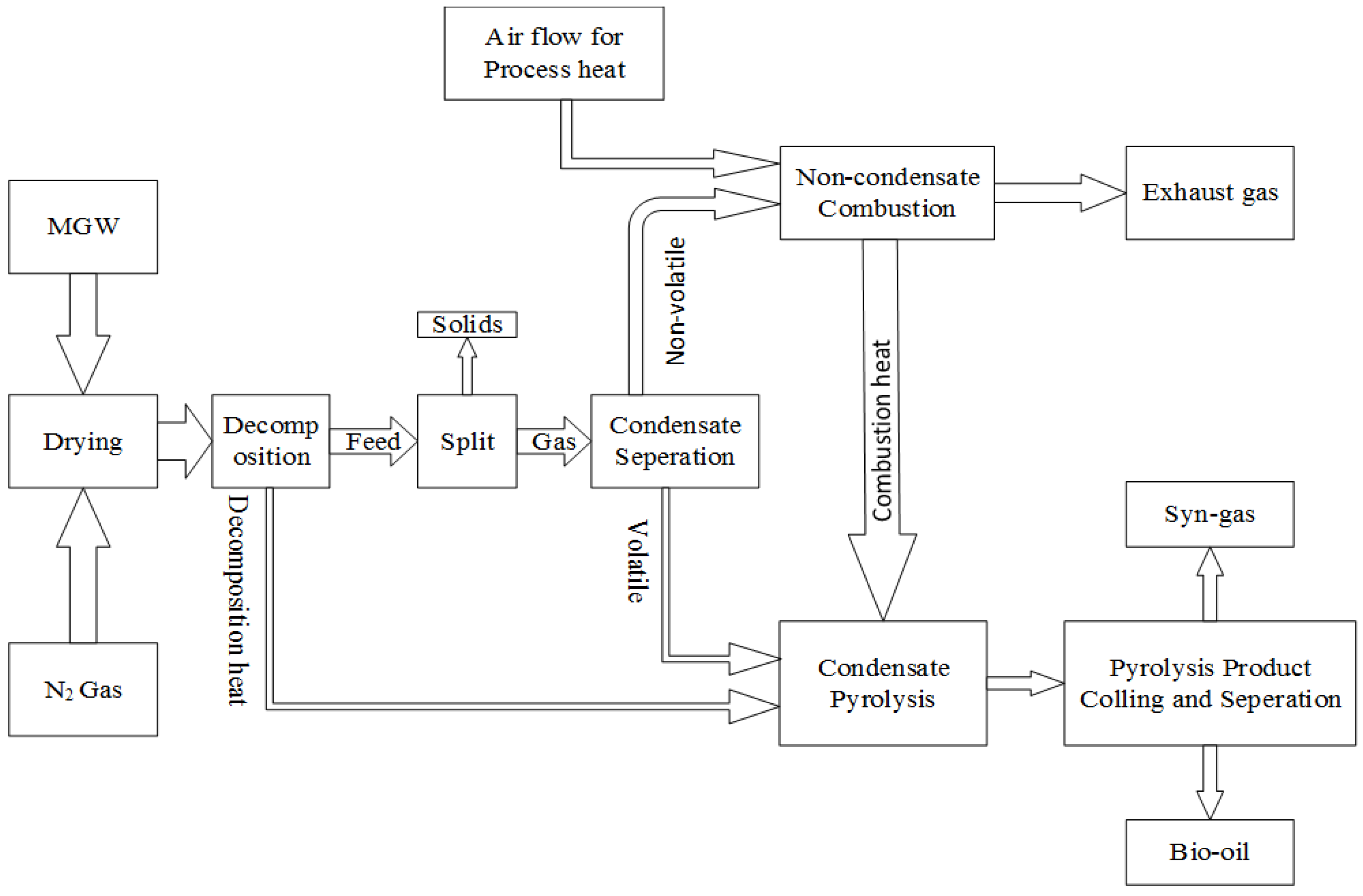
In this study, a green waste pyrolysis process was developed in four basic stages. In the first stage, the moisture content of green waste feed is reduced and, in the second stage, biomass is decomposed according to its elemental constituents. In the third stage, volatile matter and non-volatile components are separated. In the fourth stage, pyrolysis reactions are modelled using the Gibbs free energy minimisation approach [21]. The Aspen Plus process simulator does not have a built-in pyrolysis model, so a number of reactor types were defined in Aspen Plus. A pyrolysis process diagram is presented in Figure 4. An Aspen Plus model was developed based on this pyrolysis process flow diagram. The basic assumptions incorporated to make the model feasible are steady state kinetic free equilibrium model, isobaric process, all sulphur goes to H2S, no oxides of nitrogen are produced, non-condensable gas is burned for pyrolysis heat, liquid (condensate) phase was considered for pyrolysis, and ash analysis is not considered.
Figure 4. Flowsheet of MGW pyrolysis.
Energies 08 07522 g004

3.1. Model Development

In Aspen Plus software, each unit functioning block is solved as per certain sequences. This simulation software consists of several unit operation blocks, which are models of specific process operations (reactors, combustor, cyclone, heater, etc.). The built in physical properties database assists to perform the simulation calculations. These blocks were placed on a flowsheet by specifying material and energy streams. Each process is identified and broken down into its most basic components for this simulation. Once the process (all stages—chemicals and reactions) is identified, the model is constructed in the Aspen Plus environment. Following the Aspen Plus user guide, the model is created by:
  • Identifying major stages of the process and select model blocks to represent each stage.
  • Creating a flow diagram for process identification and linking streams.
  • Setting up thermodynamic and chemical properties and feed rates of each stream.
  • Setting the properties of each block.
  • Defining sensitivity calculations.
  • Running simulation and verify the results.
  • Making corrections as required and repeat the previous step.

3.2. Model Block Selection

The blocks are the most important part for the model development as the materials are altered through different physical and chemical activities. Each block requires a unique set of conditions if it is to perform correctly. A wide range of parameters including operating conditions, reactions, heat reaction calculation parameters, convergence parameters, and possible outputs need to be specified within the reactor blocks. In the Aspen Plus reactor model, blocks are classified on the basis of balance based, equilibrium based and kinetics based such as Balance based (RYield, RStoic), Equilibrium based (REquil, RGibbs), or kinetics based (RCSTR, RPlug, RBatch). In the developed model, three different types of reactor models are used. A short description with block names and block IDs of some unit operation blocks that were used in the MGW Aspen Plus pyrolysis model are described in Table 4 [22].
Table 4. Description of Aspen Plus flowsheet unit operation blocks.
Aspen Plus NameBlock IDDescription
RYIELDDECOMPConverts the non-conventional stream into conventional components.
HEATERCOOLERSimulates syn-gas cooling to a typical gas clean-up temperature.
SEP2SEPARATESimulates the CFB cyclone by separating out a specified percentage of the solid carbon.
RGIBBSCOMBUSTGibbs free energy reactor—simulates drying and pyrolysis, partial oxidation, and gasification.
BURNGibbs free energy reactor—restricts chemical equilibrium of the specified reactions to set the syn-gas composition and pyrolysis of the condensate.
SSPLITSPLITERSeparates gases from ash by specifying split fractions.

3.3. Stream Class Selection

There are three stream classes defined in Aspen Plus: material, heat and work streams. The material stream is used to classify chemical composition, thermodynamic conditions and flow rates. The heat streams are used to pass heat duties from one process unit to another. Similarly, work streams carry power between two blocks. In the current model, the MGW feed stream was defined as a non-conventional component.

3.4. Simulation

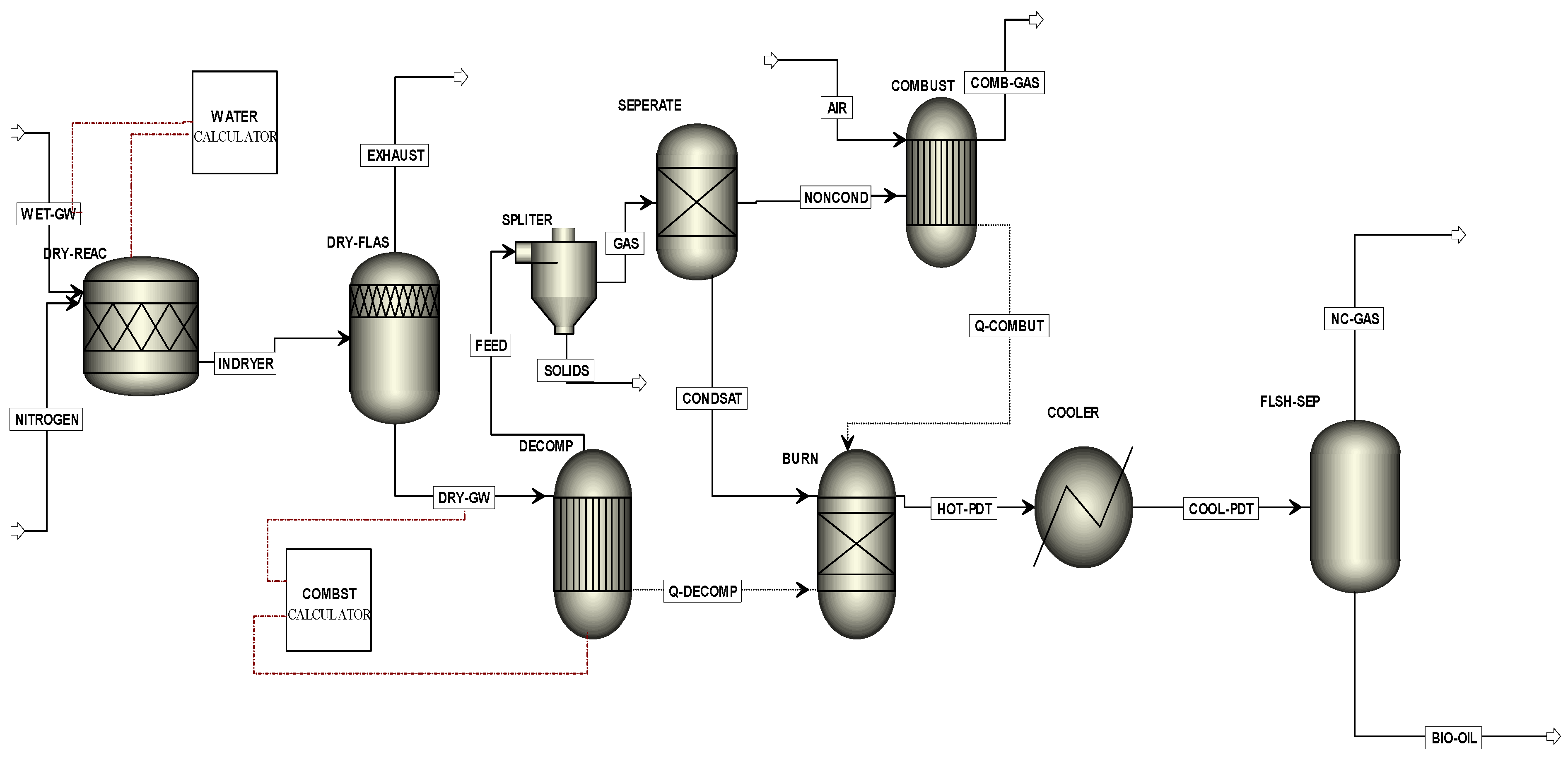
To produce the Aspen Plus model flow diagram, a series of unit operation blocks were used. The user needs to place these blocks on a flowsheet by specifying material and energy streams. The Aspen Plus computer program can quantitatively model the pyrolysis process. The process simulator does not have a built-in pyrolysis model, but it does have a number of built-in unit block models. In Aspen Plus, the blocks are chosen so that the different parts of the process can be specified as realistically as possible. The blocks are connected with proper linking streams to develop the flow diagram. The MGW pyrolysis process flow diagram is presented in Figure 5.
Figure 5. Aspen Plus model flowsheet of MGW pyrolysis.
Energies 08 07522 g005
In order to successfully run the graphical flow model in Figure 5, the basic data input was required in different stages of, for instance, global data specifications, components specifications, properties, streams, blocks. Flowsheet title, run type, input and output units, valid phases (e.g., vapour–liquid or vapour–liquid–liquid), pressure and temperature are the most commonly used setup information and they were entered in the setup specifications global sheet. Components specifications were used to specify all the components required for the simulation. Enthalpy, entropy, free energy and molar volume are computed for conventional components and conventional solids. Property models in the property method specified on the global data specification were used. Global settings include run type specification, input mode, stream class, flow basis, ambient pressure, temperature (for dynamic runs only), valid phases and free water.
Property models were specified on the Properties Advanced NC-Props form. The components specification sheet is used to select possible chemical components of the model for calculation. This sheet is used to specify all types of components such as conventional, solids, non-conventional, petroleum assays, blends, petroleum components, and hypothetical liquids in the model. Property settings of each stream and block are the most vital parts of the modelling. The properties of the stream include the material fed into the system, source, destination and behaviour of the system represents how the simulation will react. Temperature, pressure, composition and particle size distributions are also included in the stream properties. The block requires data pertaining to chemical composition, chemical reaction kinetics, reaction equilibrium, reaction stoichiometry and other characteristics, depending on the model of the block.
One of the general input requirements for the Aspen Plus pyrolysis performance model is to choose a physical property data set. Within the software there are several options for such data sets. Each option uses either different data sources and/or different methods for calculating thermodynamic properties. The property method used in the simulation is the Peng–Robinson with Boston–Mathais alpha function option. This choice reflects the recommendation of the Aspen Plus user manual. The Peng–Robinson equation of state with Boston–Mathias alpha function (PR–BM) was used in this study to estimate all physical properties of the conventional components in the pyrolysis process [23].
Nonconventional components do not participate in chemical or phase equilibrium. Therefore, enthalpy and density are calculated for nonconventional components. In this simulation, HCOALGEN and DCOALIGT use the proximate analysis, ultimate analysis, and sulphur analysis to calculate the enthalpy and density of MGW [21]. HCOALGEN and DCOALIGT models were used for enthalpy and density calculations for both green waste and ash. The process model considers the mass balances for compounds and reactors. The property specification sheet is used to specify the global property methods and models for calculation. The Peng–Rob property method was used for hydrocarbons and light gases, such as carbon dioxide, hydrogen sulphide and hydrogen. The property methods setting sheet was used to specify the physical property models and method options for each component on the Components Specifications sheet. The model has been implemented with choices of different alpha functions and has been extended to include advanced asymmetric mixing rules for hydrocarbon processing. The HCOALGEN model includes a number of different correlations, for instance, heat of combustion, heat of formation and heat capacity. In this study heat of combustion was selected for HCOALGEN and the user input value as HCOMB was chosen for the calculation method. In Figure 5, the stream “Wet-GW” was specified as a non-conventional stream and the ultimate and proximate analyses were entered. Thermodynamic conditions and mass flow rates were also entered. Inert nitrogen gas was used for the fluidised beds reactor. Nitrogen is used as inert gas due to its high natural abundance (about 77% in air) and low relative cost. In the first stage, heating and drying of the raw feed material were performed. The “RStoic” block was used for instantaneous drying of the green waste. A FORTRAN subroutine “water calculator” was used for reducing moisture from feed materials. Due to the presence of high quantities of dust particles in the green waste, the authors used a “Flash2” separator to remove the dust particles.
There are two general approaches to creating an equilibrium model: Stoichiometric and non-stoichiometric [20]. The stoichiometric approach needs a clearly defined reaction mechanism. On the other hand, no particular reaction mechanisms are involved in the non-stoichiometric approach. In the non-stoichiometric approach, the only input needed to specify the feed is its elemental composition or ultimate analysis data. The non-stoichiometric equilibrium model is based on minimising Gibbs free energy in the system without specifying the possible reactions taking place. The RYIELD reactor block was used for the pyrolysis/devolatilization part of the modelling. “RYIELD” converts the feed material into its constituting elements, including carbon, hydrogen, oxygen, nitrogen, sulphur and ash, by specifying the yield distribution according to the green waste ultimate analysis [24]. A separate column model was used to separate the condensate materials and solids in order to perform the volatile reactions. Non-stoichiometric Gibbs free energy equilibrium based splitter model was used for solid yield separation. In this study, the non-condensable gases have been used for the heat, which drives the MGW pyrolysis process. As suggested by Ramzan et al. [23] and Kabir et al. [25], the “RGIBBS” reactor model was used for condensable vapour combustion in the absence of air with the assumption that volatile reactions follow the Gibbs free energy equilibrium. It was assumed that the total yield of volatile products was equal to the volatile content of the green waste and that all the sulphur in the green waste reacts with H2 to form H2S. After cooling, the outlet streams of the RGibbs reactor enter into a flash separator block, which separates tar or oil from syn-gas.

3.5. Simulation Results and Model Validation

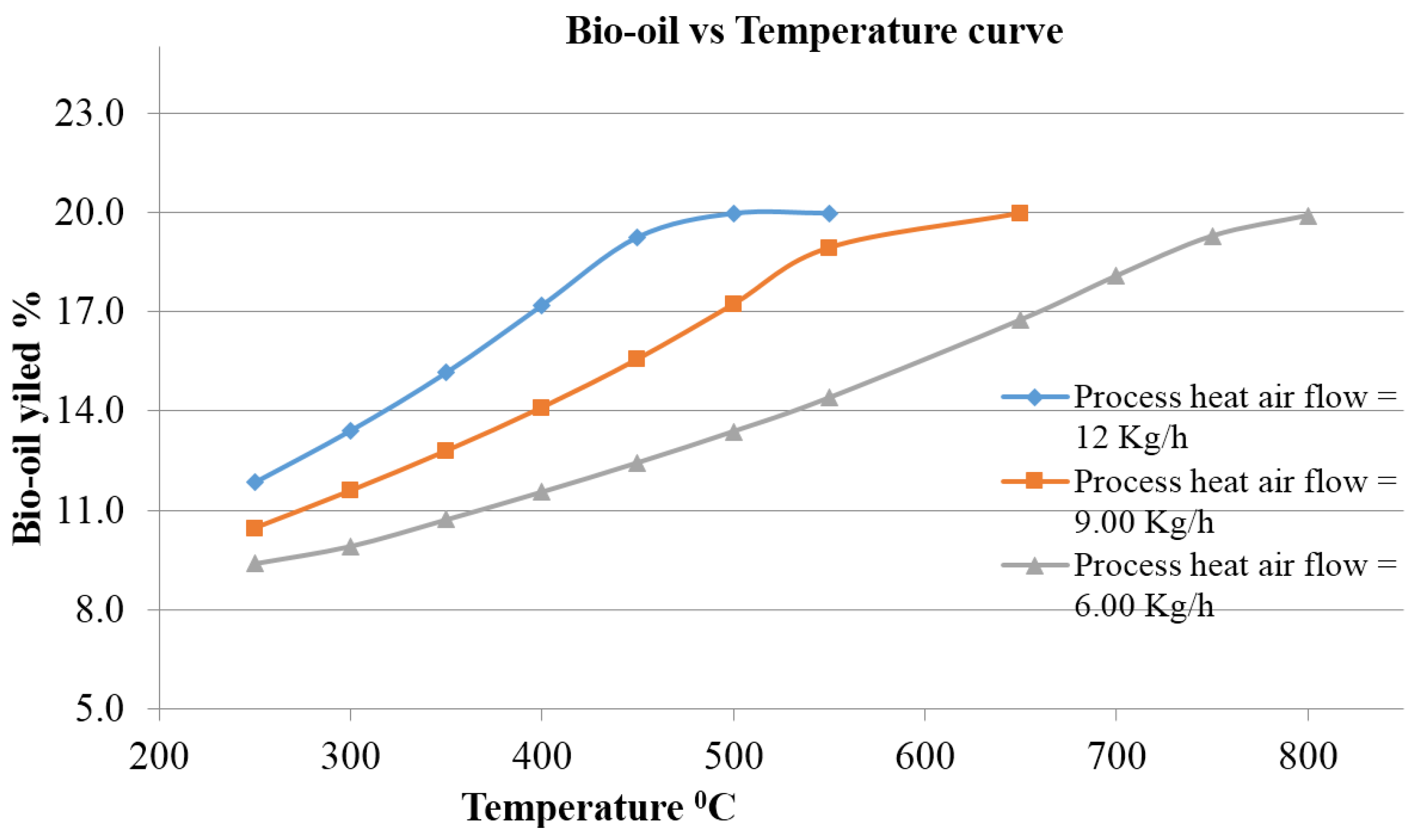
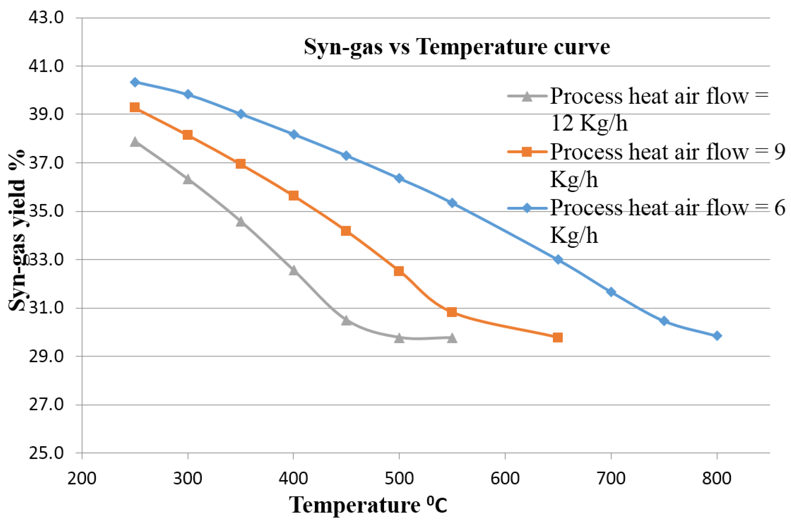
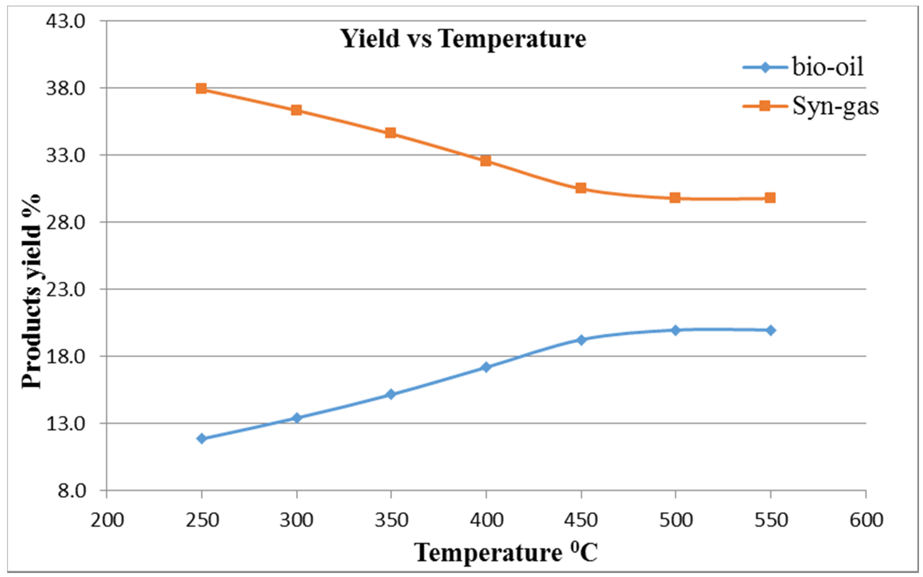
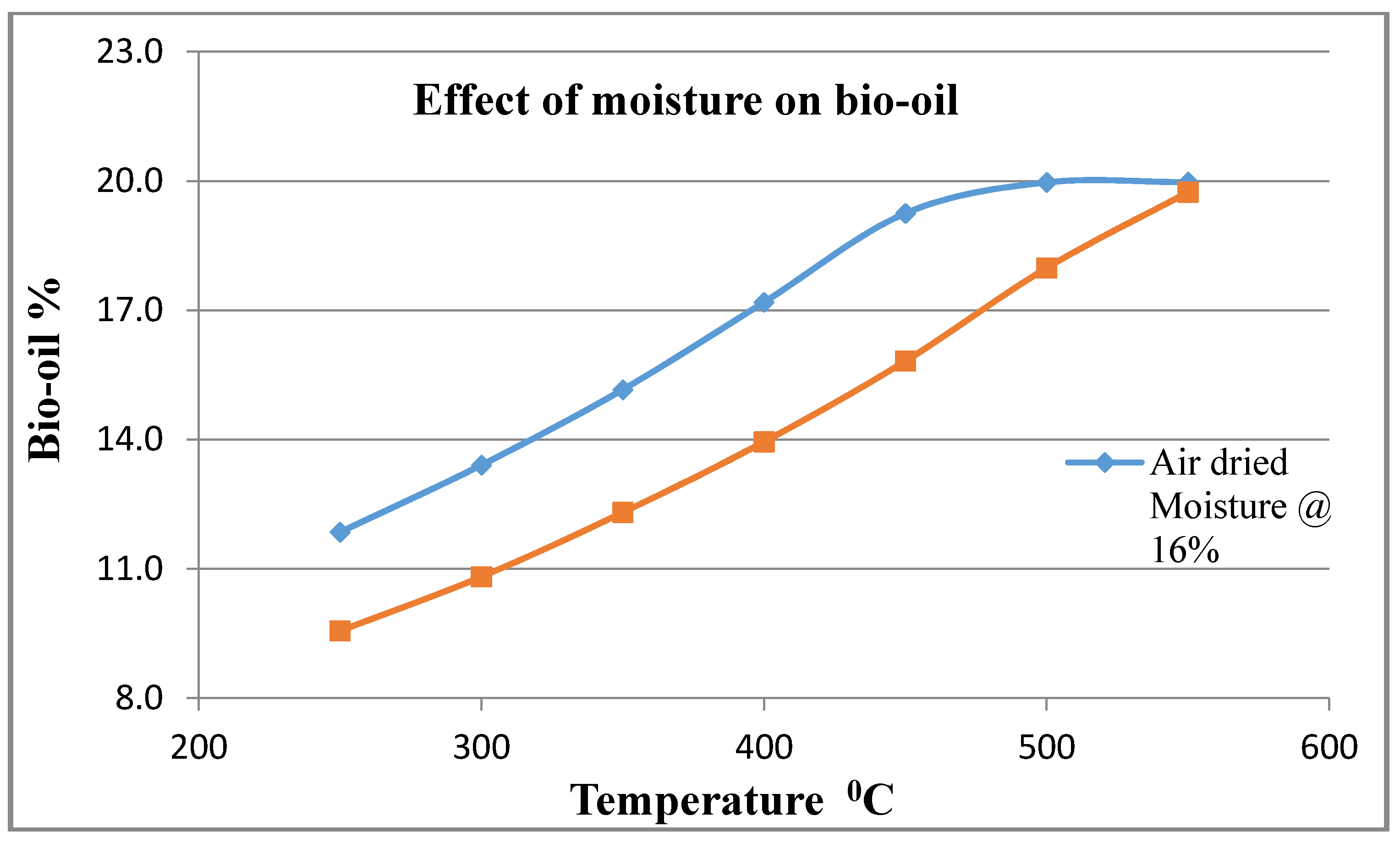
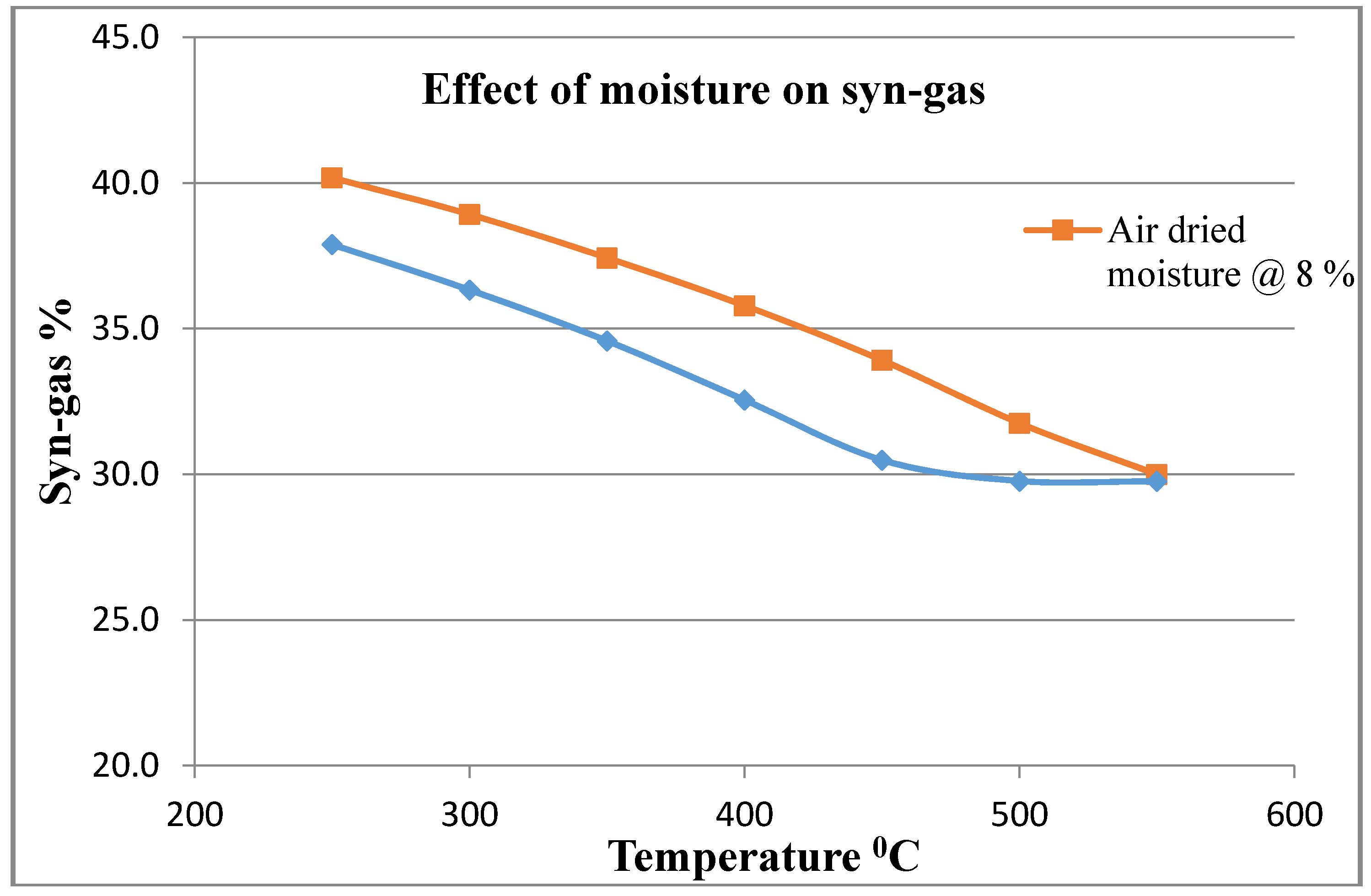
The pyrolysis of MGW was carried out in a series of trials by varying the temperature from 250 to 750 °C, particle size from 1 to 32 mm diameter, with nitrogen gas flow rate of 34.02 kg/h and initial feedstock sample flow rate at 6 kg/h. The thermal decomposition was performed at 500 °C at atmospheric pressure. The simulation process was generated by burning non-condensable gaseous products. In this simulation, maximum bio-oil was found at a reactor temperature of 500 °C at an air flow of 12 kg/h. It can also be observed that a higher temperature is needed when the air flow rate is less. The simulation model’s basic results data and a comparison between experimental results vs. model yield distributions are shown in Table 5 and Table 6, respectively. The Table 6 indicates that there are some variations between the simulated results and the experimental values. The variations are most probably due to some external and internal causes into the simulation input data. However, the differences are reasonable since the variations for carbon, hydrogen, nitrogen, and sulphur are only 7.3%, 15.82%, 7.04% and 5.56%, respectively. The presence of impurities and dust particles in the supplied feedstock may explain the discrepancies between the experimental and simulation results. Ash analysis, and the presence of impurities and dust particles were not considered in the simulation data and this may be another possible cause for the discrepancies.
Table 5. Some MGW pyrolysis yield products data from Aspen Plus simulation at 500 °C, process heat airflow 12 kg/h and one atmospheric pressure.
Mass Flow (kg/h)Bio-OilSyn-GasBio-Char
H2O (kg/h)0.36459410.06462010.1305779
N2 (kg/h)1.10 × 10−127.20 × 10−60.0117729
O2 (kg/h)4.17 × 10−172.41 × 10−80.6402156
C (kg/h)1.4-2.47
S (kg/h)0.0113372.30 × 10−82.98 × 10⁻³
SO2 (kg/h)2.13 × 10−92.43 × 10−60
H2 (kg/h)000.0911988
Temperature K323.15323.15773.15
Pressure atm1.0002761.0002761.000276
Enthalpy cal/g−3787.731−2180.099−182.3073
Entropy cal/g·K−2.1389150.02089320.642707
Density g/cc0.9695111.56 × 10−31.89 × 10⁻⁴
Total Flow kg/h1.1983281.3922862.452687
Table 6. Comparison between elemental compositions of MGW experimental results and model predictions.
Elemental Composition (Mass %)ExperimentModelVariation
C46.60%43.20%7.3%
H25.50%6.37%15.82%
N20.71%0.66%7.04%
S0.18%0.19%5.56%
O247.01%50.24%6.86%

4. Discussion on Process Optimization

The thermal degradation products of MGW were classified into three groups: Tar or bio-oil, syn-gas, and solids or bio-char. The MGW pyrolysis test results indicate that the percentages by weight of charcoal, non-condensable gas and pyrolysis oil are 48.4%, 31.7% and 19.9%, respectively. The corresponding figures from the simulation model are 40.88% (bio-char), 29.79% (syn-gas) and 19.97% (bio-oil). There are variations of less than 5.5% between the measured and simulation results of both the latter two yield products. However, the experimental bio-char quantity differs by about 15.5% from the simulation results. Table 7 shows the proximate analysis and the ultimate analysis and dry gross calorific value of the charcoal. The high ash yield of the charcoal (54.9%) indicates a high amount of extraneous materials were remained on the sample collected from the local council landfill. However, it is unlikely to be true that the collected MGW sample contains more dust and moisture than actual woody biomass. Feedstock with higher ash content, and/or lower volatile content, tend to produce less syn-gas and have a higher bio-char yield [26]. The organic component of the condensate had typical carbon (5.1%) content. Lower carbon content causes relatively lower amounts of pyrolysis oil. On the other hand, the condensate stream contained around 4.1% organic contents (noting that it is very difficult to obtain a complete collection). Overall, there is a fair agreement between the experimental and simulation results.
Charcoal, condensate and non-condensable gas are terms used in the Aspen Plus model. They are equivalent to bio-char, bio-oil (or pyrolysis oil) and syn-gas, respectively. Pyrolysis oil is a complex mixture of oxygenated compounds, carbonyls, carboxyls and phenolics. It has some limitations with respect to fuel quality, phase separation, stability, fouling issues on thermal processing and economic viability. High moisture content and viscosity are important issue when using the bio-oil as a fuel.
Table 7. Characteristics of the Bio-char produced from MGW.
PropertyValue
Proximate analysis (wt/wt %, dry basis)Air dried moisture0.48
Ash yield54.90
Volatile matter12.20
Fixed carbon32.90
Ultimate analysis (wt/wt %, dry basis)C36.60
H1.60
O60.00
N0.74
S0.15
Cl0.18
High Heating Value(dry basis, MJ/kg)13.70
Although low water content and low NOx content can improve bio-oil’s flow characteristics, these can also lower the heating value of the fuel. Unfortunately, due to its poor volatility, high viscosity, coking tendency, and high corrosiveness, the commercial standards of bio-oils have not yet enabled it to be a substitute fuel in standard equipment such as boilers, engines and gas turbines. Bio-char is an amorphous carbon matrix generated through thermal degradation of lignin and hemicelluloses, which has promising fuel characteristics. At low temperatures (450–500 °C), bio-char quantity is high due to low devolatilisation rates and low carbon conversion [27]. Studies found that reactor type and shape, feedstock type, feedstock particle size, feedstock drying treatment, heating rate, residence time, pressure and inert gas flow rates have considerable influence on bio-char’s physical characteristics [28,29]. Syn-gas consists mainly of hydrogen (H2), carbon monoxide (CO), carbon dioxide (CO2), water, and nitrogen (N2). Ash percentage and high moisture content have an adverse effect on the production of syn-gas from MGW. Hydrogen and CO in syn-gas are important factors that determine its possible applications. Pyrolysis reaction temperature is a critical issue for optimisation of syn-gas production. It was found that particle size had no influence on the pyrolysis product parameters. These results are in agreement with findings reported in the literature for grape and olive bagasse [30] and for C. Cardunculus L. [31].

4.1. Effect of Process Heat Airflow

The combustion process in this pyrolysis simulation occurred in two ways. Firstly, non-condensate combustion where burning happened in the presence of direct air which is mentioned in the simulation process as “process heat air flow”, and secondly condensate combustion in accordance with the pyrolysis principle i.e., in absence of air. The generation of combustion heat in the simulation process involved burning of non-condensable gaseous products. For this purpose, 6–12 kg/h process heat air flow has been used for maximising pyrolysis yields and the optimum reactor temperature varied with the process heat air flow rate because this rate controls the combustion of non-condensate materials.
The effects of process heat air flow on bio-oil and syn-gas yields are shown in Figure 6 and Figure 7. It can be seen from Figure 5 that the percentage of bio-oil yield products increases with an increase in air flow at certain non-condensable gas reactor temperatures. In this simulation, maximum bio-oil yield was found at a reactor temperature of 500 °C and an air flow of 12 kg/h. It can also be seen that higher temperatures are needed when air flow rates are lower. Specifically, 20% bio-oil can be produced at 650 °C when process heat air flow is 9 kg/h and at 800 °C when process heat air flow is 6 kg/h. It is also apparent that, when air flow increases, the percentage of bio-oil yield products also increases due to proper combustion of non-condensable gas. It can be seen from Figure 7 that, at a given temperature, the percentage of syn-gas decreases when the process heat air flow rate increases. It is also apparent that, at higher process air flow rates, the percentage of syn-gas production is more stable at lower temperatures than at lower process air flow rates.
Figure 6. Effect of process heat air flow effect on bio-oil.
Energies 08 07522 g006
Figure 7. Effect of process heat air flow effect on syn-gas.
Energies 08 07522 g007

4.2. Effect of Temperature

Temperature has a noticeable effect on pyrolysis yields. The essential constituents of bio-oil are furans, phenols, organic acids, ketones and higher alkanes. Alcohol and pyranoglucose are produced from cellulose pyrolysis and ketones come from hemicellulose pyrolysis. It can be seen from Figure 8 that an increase in temperature leads to an increase in bio-oil yields and a decrease in syn-gas yields. The bio-oil yield peaks at 500–550 °C. Ash and fixed carbon percentages increase with increases in temperature; consequently, there is a decrease in syn-gas. The syn-gas percentage decreases from 250 to 400 °C and it becomes stable from 450 to 550 °C. It is believed that the quantity of syn-gas will increase with increases in temperature after 550 °C. High ash content and unclean feed materials, which contain different minerals, may account for decreases in syn-gas percentage at temperatures between 250 and 400 °C. Wood charcoal dry gross calorific value usually varies between 32 and 34 MJ/kg [32]. The lower amount of charcoal dry gross calorific value (13.70 MJ/kg) indicates the MGW feedstock contained extraneous materials.
Figure 8. Yield products vs. temperature curve.
Energies 08 07522 g008

4.3. Effect of Moisture Content

Moisture content has a significant impact on pyrolysis times, temperatures and yields. Bryden and Hagge (2003) found that increases in moisture content and shrinkage can increase pyrolysis times by approximately 3%–8%. Tar yield increases and light hydrocarbon yield decreases if moisture and shrinkage work together. If they work separately, then tar yield can decrease by approximately 2%–5% with increases in moisture content [33]. It can be clearly seen from Figure 9 that, at 16% moisture content in feedstock, the bio-oil yield reaches a maximum of 20% at 500 °C and it will then remain unchanged. On the other hand, the percentage of syn-gas increases when the moisture content decreases as shown in Figure 10.
Figure 9. Effect of moisture on bio-oil.
Energies 08 07522 g009
Figure 10. Effect of moisture on syn-gas.
Energies 08 07522 g010

4.4. Effect of Particle Size Distribution

In the MGW pyrolysis simulation, particle size was assumed to be 1–32 mm.
It was found that particle size had no influence on the pyrolysis product parameters. These results are in agreement with findings reported in the literature for grape and olive bagasse [30] and for C. Cardunculus L. [31].

5. Conclusions

In this study, pyrolysis of MGW was investigated both experimentally and numerically. It was found from the experimental investigation that approximately 19.972% bio-oil, 40.83% bio-char and 29.77% syn-gas can be produced from the referenced MGW. A four-stage steady state simulation model was developed for pyrolysis process performance simulation using Aspen Plus software. A detailed procedure for creating the Aspen Plus model for the pyrolysis process using MGW is presented. Model assumptions, simulation stages, Aspen Plus block and class selection and simulation techniques are discussed. To simplify the process, ash analysis data was not incorporated within this model. The comparison of the Aspen Plus simulation results with the experimental results and the effects of temperature, process heat air flow, and the moisture content of feed materials on pyrolysis yield products are analysed and discussed. It is to be noted that a good agreement between simulation and experimental results was found. Variation of elemental compositions of MGW between simulation and experimental results were found to be 7.3% for carbon, 15.82% for hydrogen, 7.04% for nitrogen and 5.56% for sulphur.
The validated model was used to optimise the biofuel production from MGW as a function of operating variables, namely temperature, moisture content, particle size and process heat air–fuel ratio. It was found from the simulation results that the bio-oil yield percentage increases with the pyrolysis temperature from 250 to 500 °C, then remains unchanged up to 550 °C, and decreases after 600 °C. However, syn-gas yield percentages behave oppositely. It may be considered that bio-oil production is maximised between pyrolysis temperatures of 500 and 550 °C. For maximising pyrolysis yields, the optimum reactor temperature varies with the process heat air flow rate because this rate controls the combustion of non-condensate materials. The moisture content of the raw feedstock can significantly impact on pyrolysis times and pyrolysis temperatures. Increases in moisture content can increase pyrolysis oil yields and decrease the syn-gas yields.
Reducing complexity and ensuring short computational times, the Aspen Plus simulator provides a useful design aid in evaluating a complex reacting system. It gives important insights about optimising different process parameters. These results reveal that the production of bio-fuel through the pyrolysis process from MGW will be a competitive alternative source of fossil fuel. Biofuel production through the pyrolysis process is not fully commercially established yet, but it has a lot of potential to become a suitable energy recovery option.

Acknowledgments

Authors would like to thank Central Queensland University, Australia for funding this project. Many thanks to CSIRO’s Australian Minerals Research Centre and Biomass Energy Services & Technology (BEST) Pty Ltd., Australia for carrying our MGW sample pyrolysis test works.

Author Contributions

First author of the paper performed experimental analysis, and modelling and simulation including discussion on process optimization. Second author compiled the whole manuscript including literature review for feedback from other authors and third author supervised the whole thing and provided feedback for improvement from the original manuscript.

Conflicts of Interest

The authors declare no conflict of interest.

References

  1. Zhang, O.; Chang, J.; Wang, T.; Xu, Y. Review of biomass pyrolysis oil properties and upgrading research. Energy Convers. Manag. 2007, 48, 87–92. [Google Scholar] [CrossRef]
  2. Berndes, G.; Hoogwijk, M.; Broek, R.V. The contribution of biomass in the future global energy supply: A review of 17 studies. Biomass Bioenergy 2003, 25, 1–28. [Google Scholar] [CrossRef]
  3. Ramage, J.; Scurlock, J. Biomass. In Renewable Energy-Power for a Sustainable Future; Boyle, G., Ed.; Oxford University Press: Oxford, UK, 1996. [Google Scholar]
  4. Demirbas, A. Waste management, waste resource facilities and waste conversion processes. Energy Convers. Manag. 2011, 52, 1280–1287. [Google Scholar] [CrossRef]
  5. Tsai, W.T.; Lee, M.K.; Chang, Y.M. Fast pyrolysis of rice husk: Product yields and compositions. Bioresour. Technol. 2007, 98, 22–28. [Google Scholar] [CrossRef] [PubMed]
  6. Gaijing, Z.; Weiding, L. A key review on energy analysis and assessment of biomass resources for a sustainable future. Energy Policy 2010, 38, 2948–2955. [Google Scholar]
  7. Demirbas, A. Biomass resource facilities and biomass conversion processing for fuels and chemicals. Energy Convers. Manag. 2001, 42, 1357–1378. [Google Scholar] [CrossRef]
  8. Oliver, G. Efficiency of energy recovery from municipal solid waste and the resultant effect on the greenhouse gas emission. Waste Manag. Res. 2009, 27, 894–906. [Google Scholar]
  9. Goyal, H.B.; Saxena, R.C.; Seal, D. Thermochemical Conversion of Biomass to Liquids and Gas; Haworth Press: Binghamton, NY, USA, 2006. [Google Scholar]
  10. Asadullah, M.; Rahman, M.A.; Ali, M.M.; Motin, M.A.; Sultan, M.B.; Alam, M.R. Production of bio-oil from fixed bed pyrolysis of bagasse. Fuel 2007, 86, 2514–2520. [Google Scholar] [CrossRef]
  11. Islam, M.N.; Beg, M.R. The fuel properties of pyrolysis liquid derived from urban solid wastes in bangladesh. Bioresour. Technol. 2004, 92, 181–186. [Google Scholar] [CrossRef] [PubMed]
  12. Jahirul, M.J.; Rasul, M.G.; Chowdhury, A.A.; Ashwath, N. Biofuels production through biomass pyrolysis—A technological review. Energies 2012, 5, 4952–5001. [Google Scholar] [CrossRef]
  13. Cottam, M.L. Technical and Economic Simulation of Biomass Pyrolysis Processes for Fuels and Electricity. Ph.D. Thesis, Aston University, Birmingham, UK, 1995. [Google Scholar]
  14. Kabir, M.J.; Rasul, M.G.; Ashwath, N.; Chowdhury, A.A. Environmental impacts of green wastes to energy conversion through pyrolysis process: An overview. In Proceedings of the 5th BSME International Conference on Thermal Engineering, Dhaka, Bangladesh, 21–23 December 2012.
  15. Ashwath, N.; Rank, A.H. Bioenergy and charcoal production: An alternative option for disposal of combustible municipal wastes. Int. J. Environ. Waste Manag. 2010, 6, 71–81. [Google Scholar] [CrossRef]
  16. Schobert, H. Chemistry of Fossil Fuels and Biofuels; Cambridge University Press: Cambridge, UK, 2013. [Google Scholar]
  17. Fegbemi, L.; Khezami, L.; Capart, R. Pyrolysis products from different biomasses: Application to the thermal cracking of tar. Appl. Energy 2001, 69, 293–306. [Google Scholar] [CrossRef]
  18. Heo, S.H.; Park, J.H.; Park, Y.; Ryu, C.; Suh, J.D.; Suh, Y.; Yim, J.; Kim, S. Bio-oil production from fast pyrolysis of waste furniture sawdust in a fluidized bed. Bioresour. Technol. 2010, 101, 91–96. [Google Scholar] [CrossRef] [PubMed]
  19. Yin, R.; Liu, R.; Mei, Y.; Fei, W.; Sun, X. Characterization of bio-oil and biochar obtained from sweet sorghum bagasse fast pyrolysis with fractional condensers. Fuel 2013, 112, 96–104. [Google Scholar] [CrossRef]
  20. Puing-Arnavat, M.; Brunio, J.C.; Coronas, A. Review and analysis of biomass gasification models. Renew. Sustain. Energy Rev. 2010, 14, 2841–2851. [Google Scholar] [CrossRef]
  21. Aspen Technology, Inc. Aspen Plus—Getting Started Modeling Processes with Solids, Version Number: V10.2; Aspen Technology, Inc.: Bedford, MA, USA, 2010.
  22. Doherty, W.; Reynolds, A.; Kennedy, D. The effect of air preheating in a biomass CFB gasifier using Aspen Plus simulation. Biomass Bioenergy 2009, 33, 1158–1167. [Google Scholar] [CrossRef]
  23. Ramzan, N.; Ashraf, A.; Naveed, S.; Malik, A. Simulation of hybrid biomass gasification using Aspen Plus: A comparative performance analysis for food, municipal solid and poultry waste. Biomass Bioenergy 2011, 35, 3962–3969. [Google Scholar] [CrossRef]
  24. Atnaw, S.M.; Sulaiman, S.A.; Yusup, S. A simulation study of downdraft gasification of oil-palm fronds using Aspen Plus. J. Appl. Sci. 2011, 11, 1913–1920. [Google Scholar] [CrossRef]
  25. Kabir, M.J.; Rasul, M.G.; Ashwath, N.; Chowdhury, A.A. Computational model development of municipal green waste pyrolysis using Aspen Plus software. In Proceedings of the 12th International Conference on Sustainable Energy Technologies, Hong Kong, China, 26–29 August 2013.
  26. Fahmi, R.; Bridgwater, A.V.; Donnison, I.; Yates, N.; Jones, J.M. The effect of lignin and inorganic species in biomass on pyrolysis oil yields, quality and stability. Fuel 2008, 87, 1230–1240. [Google Scholar] [CrossRef]
  27. Rocha, J.D.; Olivares-Gómez, E.; Mesa-Pérez, J.M.; Cortez, L.A.B.; Seye, O.; Brossard-González, L.E. The demonstration fast pyrolysis plant to biomass conversion in Brazil. In Proceedings of the World Renewable Energy Congress VII (WRC 2002), Cologne, Germany, 7 March 2002.
  28. Cetin, E.; Moghtaderi, B.; Gupta, R.; Wall, T.F. Influence of pyrolysis conditions on the structure and gasification reactivity of biomass chars. Fuel 2004, 83, 2139–2150. [Google Scholar] [CrossRef]
  29. González, J.F.; Román, S.; Encinar, J.M.; Martinéz, G. Pyrolysis of various biomass residues and char utilization for the production of activated carbons. J. Anal. Appl. Pyrolysis 2009, 85, 134–141. [Google Scholar] [CrossRef]
  30. Encinar, J.M.; Beltran, F.J.; Bernalte, A.; Ramiro, A.; Gonzalez, J.F. Pyrolysis of two agricultural residues: Olive and grape bagasse. Influence of particle size and temperature. Biomass Bioenergy 1996, 11, 397–409. [Google Scholar] [CrossRef]
  31. Encinar, M.J.; Gonzalez, F.J.; Gonzalez, J. Fixed-bed pyrolysis of Cynara cardunculus L. product yields and compositions. Fuel Process. Technol. 2000, 68, 209–222. [Google Scholar] [CrossRef]
  32. Demirbaş, A. Properties of charcoal derived from hazelnut shell and the production of briquettes using pyrolytic oil. Energy 1999, 24, 141–150. [Google Scholar] [CrossRef]
  33. Bryden, M.K.; Hagge, J.M. Modeling the combined impact of moisture and char shrinkage on the pyrolysis of a biomass particle. Fuel 2003, 82, 1633–1644. [Google Scholar] [CrossRef]

