Next Article in Journal
The Stability Analysis of a Multi-Port Single-Phase Solid-State Transformer in the Electromagnetic Timescale
Previous Article in Journal
Condition Monitoring and Fault Diagnosis of Wind Turbines Gearbox Bearing Temperature Based on Kolmogorov-Smirnov Test and Convolutional Neural Network Model
 
 
Addendum published on 17 January 2019, see Energies 2019, 12(2), 286.
Review

Transient Faults in Wind Energy Conversion Systems: Analysis, Modelling Methodologies and Remedies

1
Power Electronics & Renewable Research Laboratory (PEARL), Block M, Level 5, Department of Electrical Engineering, University of Malaya, Kuala Lumpur 50603, Malaysia
2
Department of Electrical Engineering, University of Malaya, Power Energy Dedicated Advanced Center (UMPEDAC), Level 4, R & D UM, Kuala Lumpur 59990, Malaysia
3
School of Software & Electrical Engineering, Swinburne, Victoria 3122, Australia
4
School of Engineering, Deakin University, Victoria 3125, Australia
5
Department of Electrical and Computer Engineering, King Abdulaziz University, Jeddah 21589, Saudi Arabia
*
Author to whom correspondence should be addressed.
Energies 2018, 11(9), 2249; https://doi.org/10.3390/en11092249
Submission received: 23 July 2018 / Revised: 14 August 2018 / Accepted: 16 August 2018 / Published: 27 August 2018
(This article belongs to the Section F: Electrical Engineering)

Abstract

:
This paper presents an in-depth review of classical and state-of-the-art models for analysing the transient stability in wind energy conversion systems. Various transient simulation models for a number of wind turbine generator (WTG) configurations are introduced, under different disturbances. The mitigation is achieved, by manipulating the generator speed and power electronics control, whereas the protection is implemented using conventional, intelligent or digital relays for the safety of sensitive components, in case of transient fault occurrence. The various control systems in WECS are basically employed to transform and regulate the varying frequency, owing to the stochastic nature of wind speed, to the standard 50-Hz or 60-Hz frequency for coupling to an existing electrical utility grid. It has been observed that the control and protection schemes in wind energy systems are concurrently applied. Transient faults in WECSs are a dominant power quality problem especially in the doubly-fed induction generator (DFIG), and often classified as overcurrent or overvoltage transients. These transients are measured using the transient stability index and analysed using the EMTDC/PSCAD software. In addition, the inertia of the rotating masses of wind turbine generators is often characterized by a transient torque, which generates oscillations in power systems.

1. Introduction

A wind turbine coupled with an induction generator introduces transients when connected to power systems; these transients have a short duration, but extremely high inrush current. This condition upsets the grid norms of operation and causes high torque spikes in the drive trains of wind turbines. In the use of direct-connected induction generators, transients become substantially high, thereby adversely affecting the grid and restricting the recommended number of wind turbines to be installed for coupling to a grid [1].
Frequent complications in coupling electrical quantities can be addressed through the application of the axis transformation analogy from the three-phase stationary a-b-c to direct-quadrature (d-q) axis, which develops in the same nature as either the two-phase stationary ds qs or the two-phase rotating frame d-q. These axis transformations significantly reduce the complications in the transient modelling and simulations of induction, particularly doubly-fed induction generators (DFIGs) [2]. Phasors can describe only steady-state conditions. Moreover, spaces are valuable for the representation of transient events.
DFIGs, which are wind turbine generators or systems with variable speed, are regularly used in power-generating systems. The power electronic converter, which supplies the rotor winding, accounts for 30% of the total rated power. The stator winding of the DFIG is typically connected directly to the grid [1], and the rotor and the stator of the turbine generator can be inexpensive sources of transients. The induction generator flux is regulated with the use of open loop control, which manipulates the direct-axis component of the stator current ( ids ) . However, the rotor flux is mainly fixed at a rated value under standard conditions for fast-transient response. In addition, the vector control technique enables fast-transient response for intelligent control schemes, such as fuzzy logic-based vector control [3].
With regard to fixed-speed wind systems with cage induction generators, the integration of the generator is usually achieved with the use of a third-order (rotor flux transient) dynamic model on the basis of rotating field theory. The d-q coordinate system is usually applied to model the induction generator [4].
Transient phenomena in stators are typically faster than rotor transients; therefore, such phenomena are commonly ignored, which is equivalent to neglecting the DC component of the transient current in the stator, thereby allowing the representation of only the fundamental frequency components [4].
The transient stability of a power system is a measure of the extent to which it can retain synchronism when exposed to several interruptions. These interruptions include equipment downtime, load variations and faults that result in large excursions of the machine rotor angles [5]. The rotor angle of the machine, which is measured according to the reference rotating synchronously, is a variable that tests the transient stability of a system. The significance of the contingency and trajectory of a system, which result from specific disruptions, can be analysed by the transient stability index (TSI) [6]. A commonly-adopted technique for determining the transient stability in a synchronous generator is the critical clearing time (CCT), which is the maximum period of fault occurrence that does not cause any loss of synchronism in a generator [4,7].
Wind turbine transient stability schemes rely on several factors, such as network variables and fault specifications. Nevertheless, wind speed is assumed constant in simulations of the transient stability of wind turbines [6]. Wind energy conversion systems (WECSs) demand generators with extremely high torque capacities owing to the large moment of inertia of the turbine blades. High-speed controllers generate high transients in the mechanical torque, which is reproduced in the general power [8]. When a wind generator ends its transients supply, its rotor speed changes from the rated value. The combination of proportional and inertial controls is another transient control method for wind turbines. This technique is applied with the use of the stored kinetic energy of the rotating masses. The surplus power, which is injected using nonconventional-type generators throughout the frequency transient, is mostly obtained from the stored energy in the rotating inertial masses of the WECS equivalence [9].
The factors that contribute to transient phenomena in wind power plants (WPPs) are not commonly encountered in traditional power plants and include the extensive application of unconventional generators, turbines and dry-type insulation transformers. The high-frequency interaction of two or more of the aforementioned equipment in a power scheme results in transients with high stresses and a potential breakdown of the insulation of the essential equipment [10]. The transient-fault detection mechanism must be selective and effective in differentiating the transients that emanate from the usual switching operations of voltage source converters and transients that arise due to fault occurrences. This situation implies that protection systems must not be miscalculated under fast-switching transient conditions, which are unrelated to faults [11].
The transient overvoltage in high-voltage direct current (HVDC) transmission applications has become a major power quality issue as large offshore wind farms are gradually becoming ubiquitous in the coastal areas of Europe; these wind farms exploit wind energy for commercial purposes. In addition to generating power, large wind farms transmit HVDCs to transport power to shores for onward distribution [12].
Offshore grid networks that adopt large cable systems are often capacitive in nature. In such networks, the use of good breaker equipment to trip, couple or decouple the cable networks correctly is important. Otherwise, charging/discharging circuits can result in switching overvoltages at a level that can stress the collection grid equipment, thereby causing the circuit breakers to prestrike or restrike. In general, high overvoltages occur due to the resonance between the nacelle transformer saturation differential inductances and the feeder cable capacitance. Thus, examining the potential effect of these lengthy cables on transient overvoltages is crucial [13].
This review is inspired to develop a control and protection technique that will modify the traditional function of the crowbar in DFIG (i.e., offering protection to the rotor-side converter (RSC) against overcurrent transients) with a new improved version, for mitigating faults in WECS. This objective can be attained by the application of an innovative and user-defined phaselet packet transform to analyse and classify transients occurring in the system as specifically related to fault or non-fault, so as to send a trip signal to the power triac to trip the affected phase, unlike typical protection systems, which failed short of this accuracy, and will trip whether the transient is related to fault or not. Another idea conceived of, with regard to the control system, is to propose a space vector pulse width modulation (SVPWM), which will be embedded into the protection scheme. The SVPWM technique is programmed to send a signal to the power triac in order to adjust its firing angle in proportion to the magnitude of the transient fault, rather than tripping it completely. This can resolve the problem of drawing reactive power from the grid, as experienced when a typical crowbar is utilized. This could have a positive economic impact, because it reduces the overall down time of the system. The intended strategy is a precursor to the plug-and-play realization in WECS, as already forecasted in [14,15].
The remainder of this paper comprises Section 2, Section 3, Section 4, Section 5, Section 6 and Section 7. Section 2 presents the models and equations that describe the principal components from which the transients in WECSs emanate. Section 3 shows the various types of transients, especially in wind turbine generators, and their stability analysis. Section 4 introduces the transient issues in HVDC transmission systems with their protection schemes. Section 5 presents several control and protection systems that are used to mitigate the negative effect of transients on power quality. Section 6 discusses the general transient problems in wind energy technology and future trends, and Section 7 reports the conclusion.

2. Transient Models of Associate Components in WECS

Transient modelling techniques of wind power plants were proposed in [10] to expound and validate the basic components of WPPs and thus assess the momentary and transient overvoltages. The simulation of such overvoltages requires the application of low simulation time steps ranging from a few nanoseconds to a few microseconds. Therefore, realization of the overall WPP is a tedious task. A single feeder of a WPP, which consists of WTGs, is often adopted to reduce the simulation time without deviating from the accuracy limit.

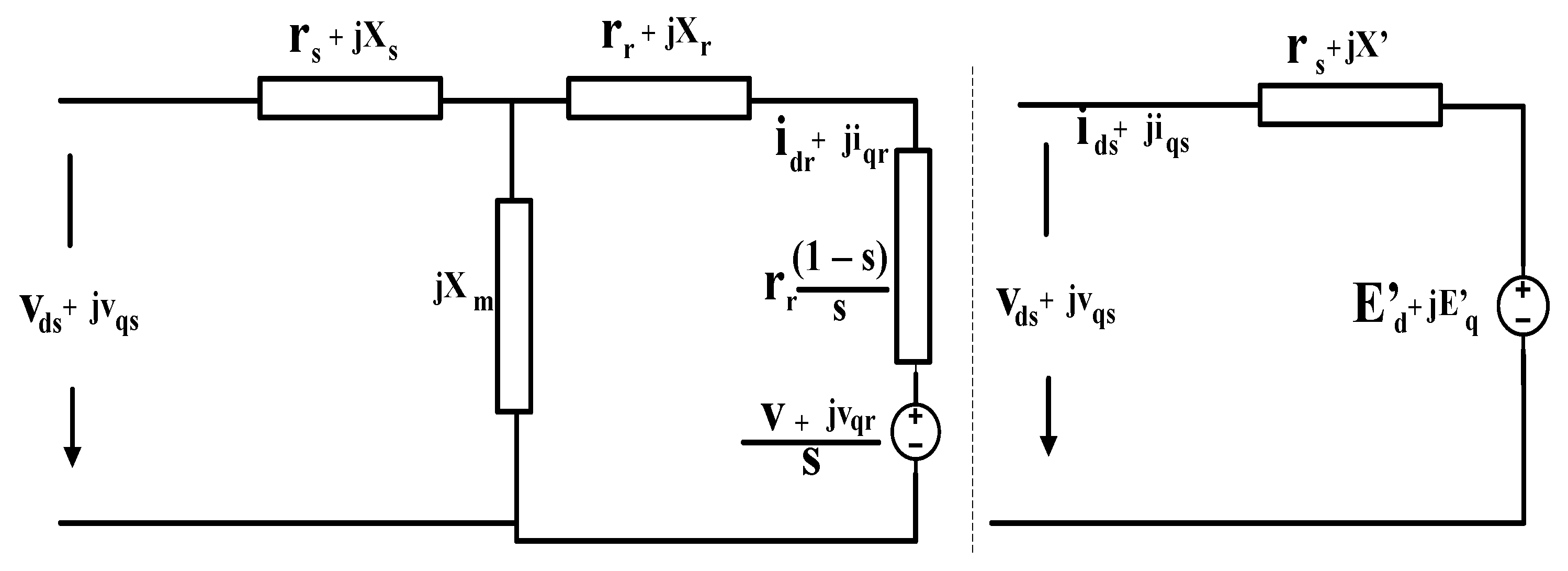
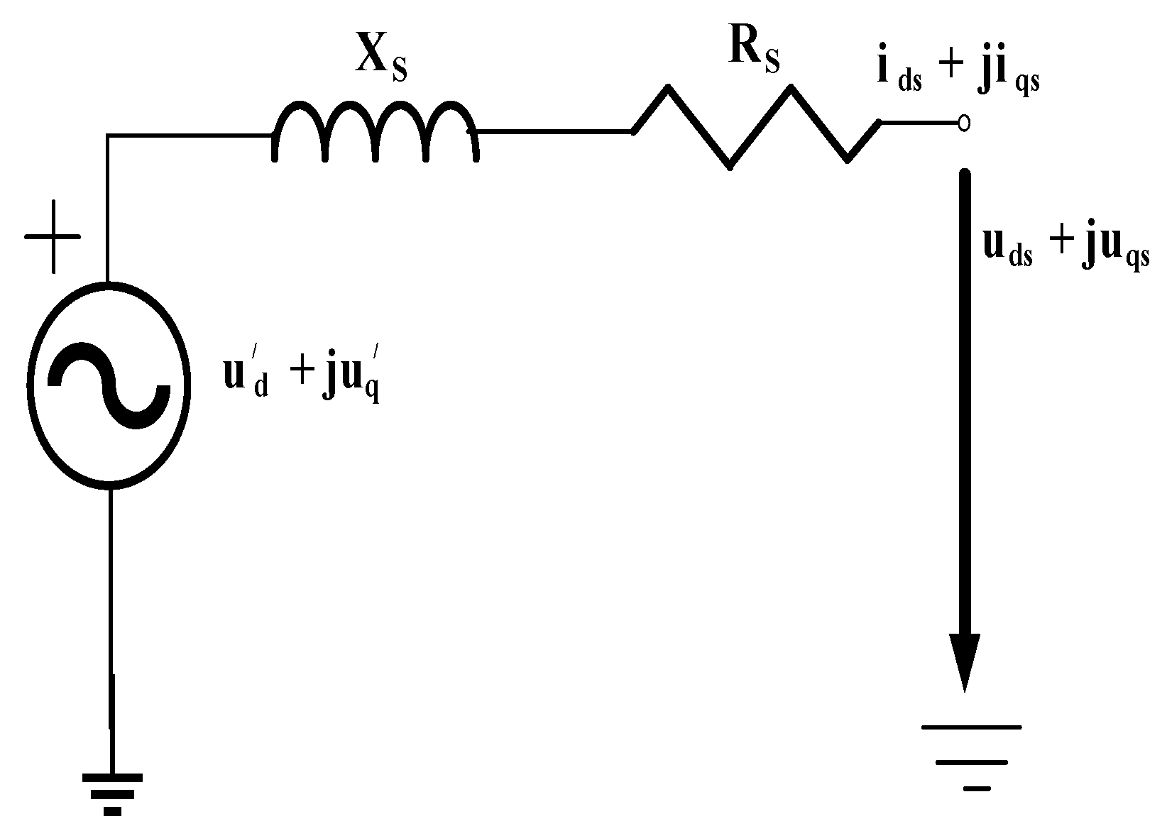
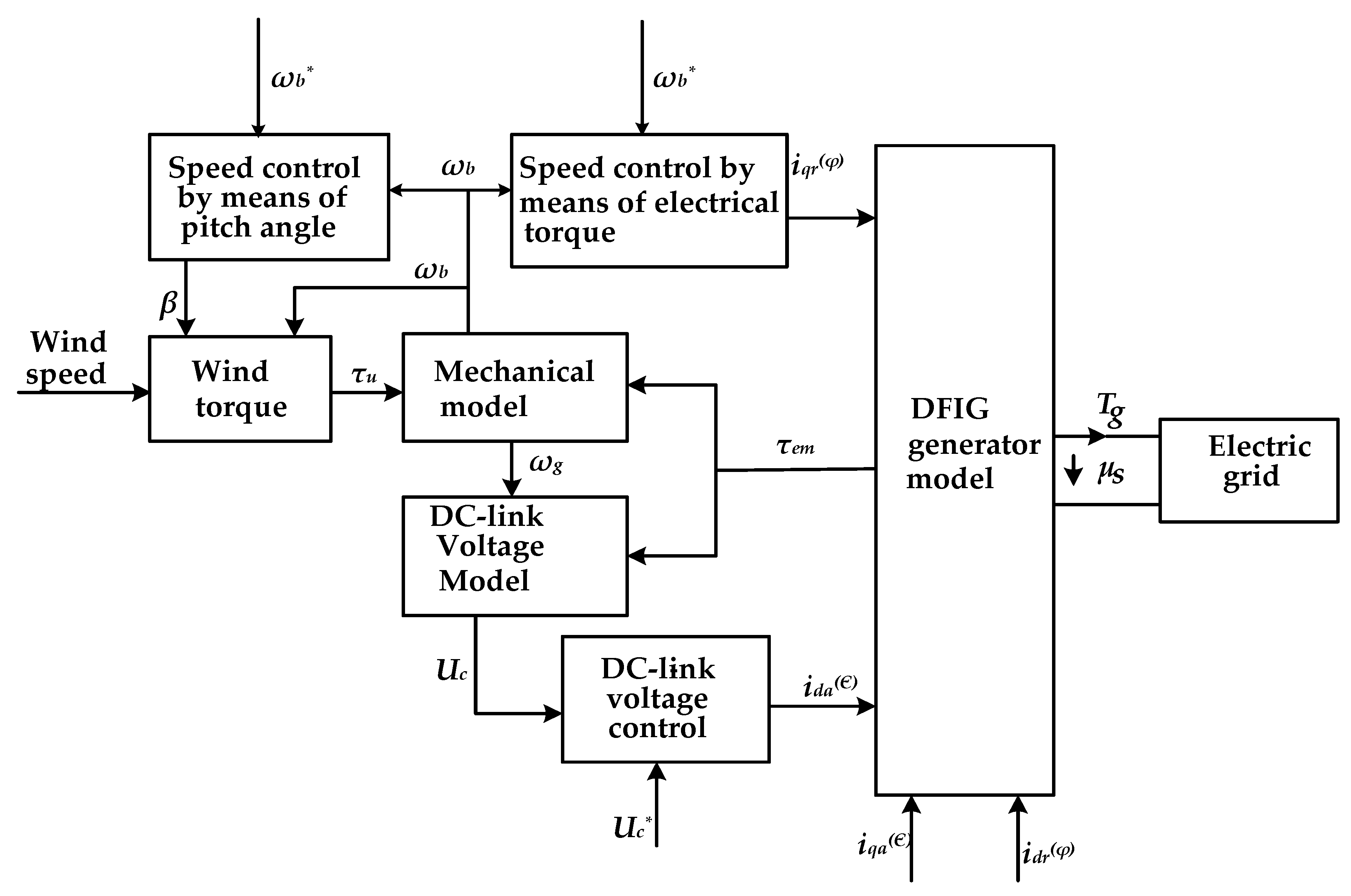
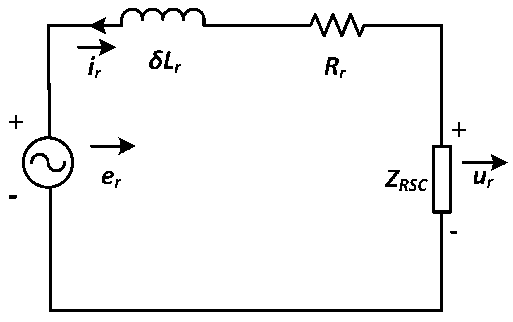
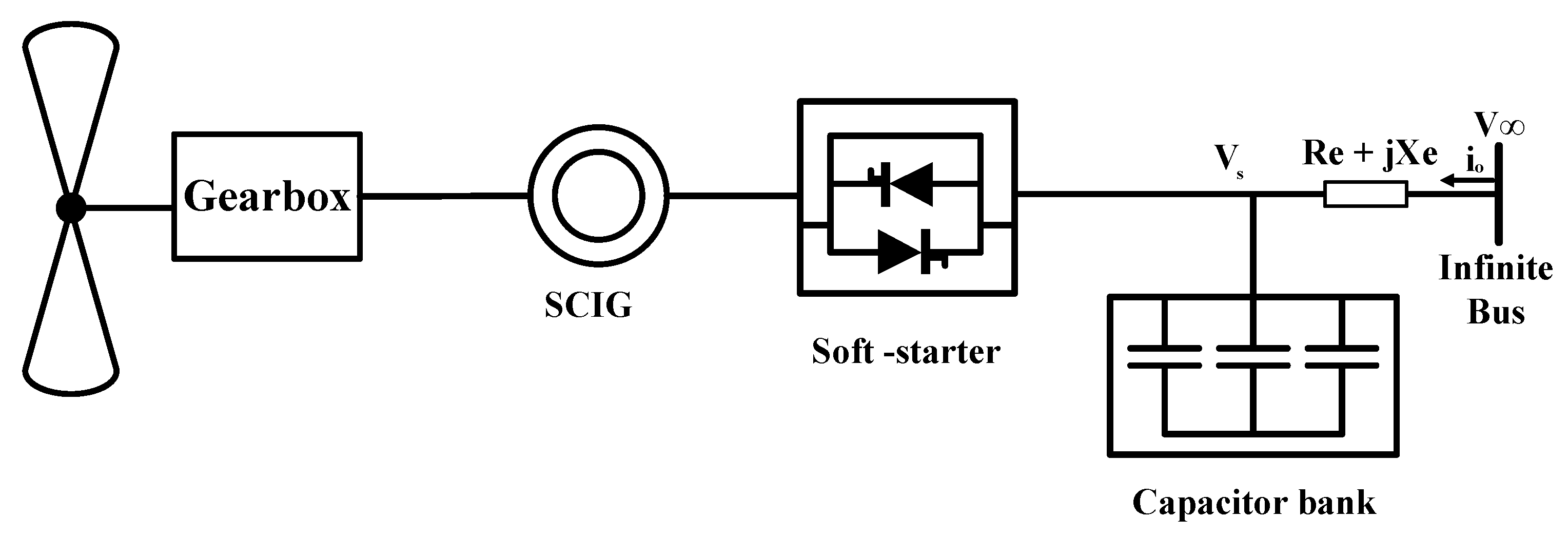
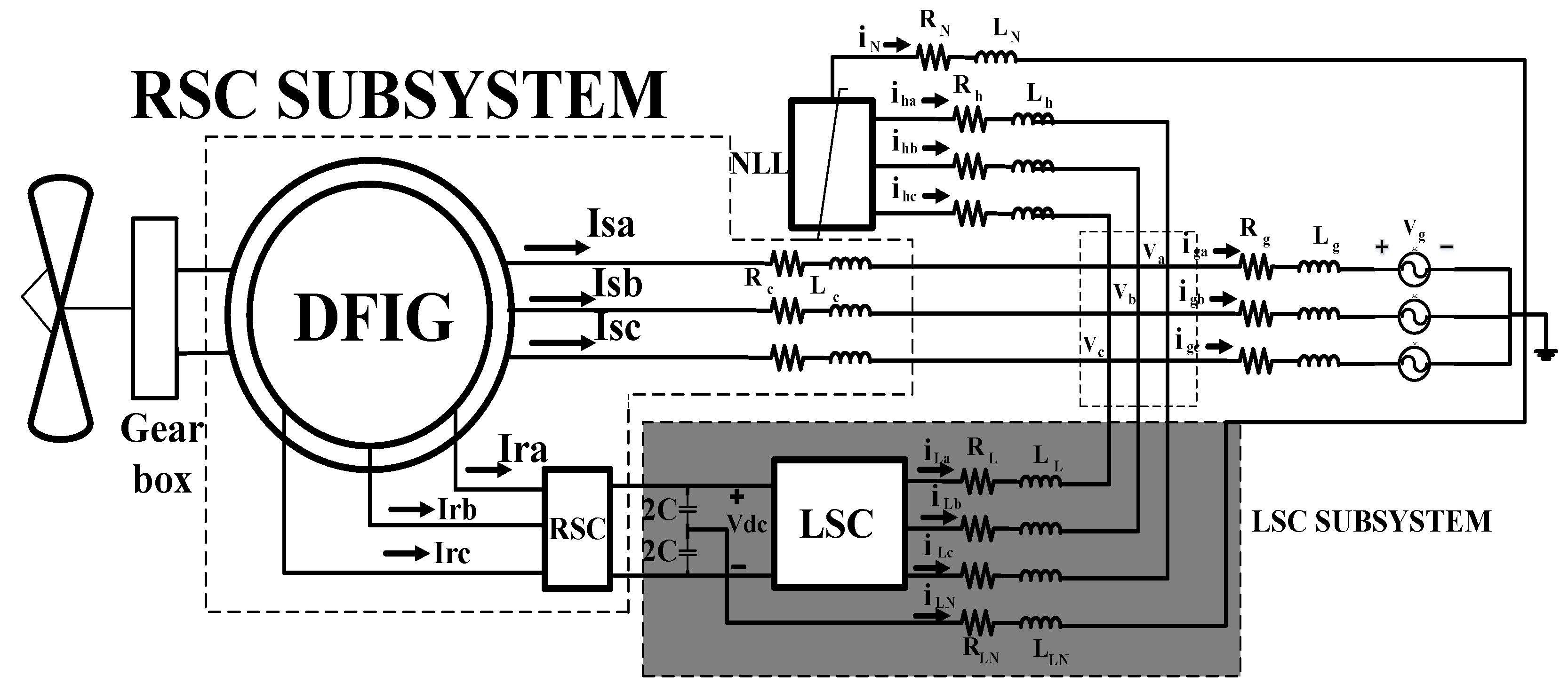
2.1. Wind Turbine Generator Transient Model

A simple model that embodies a DFIG equipped with a wind turbine, shown in Figure 1, as a voltage responsible for the transient reactance, was proposed in [16]. The DFIG was considered a typical induction generator with a small-magnitude rotor voltage. Neglecting the stator transient per unit electrical equations of the DFIG can be expressed in phasor form as in [17].
According to [1], the transient recovery of DFIGs is significantly affected by the active power oscillations generated by the shaft dynamics, which depend on the shaft stiffness.
Simplifying and reducing the converter and induction machine model do not substantially change the DFIG transient response. The erratic behaviour exhibited by DFIGs during large disturbances, when the rotor-side converter (RSC) is blocked, has been reported. Depending on the speed before the application of disturbance, a DFIG may operate anywhere during the transient, whether absorbing (i.e., motor) or delivering a rated active power. During the fault ride-through of the DFIG with a crowbar, an electromagnetic torque drops due to the decrease in voltage, which leads to rotor acceleration. The grid voltage falls steeply in magnitude, thereby leading to the generation of high-current transients in the rotor and the stator due to the magnetic coupling between the rotor and the stator [18,19]. In a previous work, a crowbar was used to short-circuit an RSC to protect it from rotor circuit overcurrent during transient disturbances [20,21].
In consideration of the typical induction machine, the rotor voltage in Equation (2a,b) was set as zero. Eliminating the rotor currents and rewriting the equation with respect to the voltage responsible for the transient reactance were essential to simplifying (1a)–(3d) to facilitate execution in a transient stability program. Therefore, Equation (5a,b) were obtained by solving (1a), (3b) and (3d) [16].
The electrical equations of the induction machines were analysed further, where a nonzero rotor voltage was encountered. A DFIG model compatible with the transient program could be obtained with the elimination of the variables associated with the flux linkage in these equations. Figure 2 shows the steady-state and dynamic equivalent circuits of the DFIG, from which the subsequent and relevant equations, namely (5a,b), could be derived [16,22].
Stator voltage:
V d s = r s i d s + ω s ψ q s
V q s = r s i q s + ω s ψ d s
Rotor voltage:
V d r = r r i d r + s ω s ψ q r + d ψ d r d t
V q r = r r i q r + s ω s ψ d r + d ψ q r d t
where:
V d s and V d r are the stator and rotor voltages amplitude of the d-component, V q s and V q r are the stator and rotor voltages of the q-component, ψ d s and ψ d r are the stator and rotor fluxes of the d-component, ψ q s and ψ q r are the stator and rotor fluxes of the q-component, i d s and i d r are the stator and rotor currents of the d-component, i q s and i q r are the stator and rotor currents of the q-component, r s and r r are the stator and rotor resistances, ω s is the stator angular velocity and s is the rotor slip.
Flux linkage:
ψ d s = L s s i d s + L m i d r
ψ q s = L s s i q s + L m i q r
ψ d r = L m i d s + L r r i d r
ψ q r = L m i q s + L r r i q r
where L m is the magnetizing inductance and L s s and L r r are the self-inductances of the stator and rotor, respectively.
Electromagnetic torque:
T e m = ψ q r i d r ψ d r i q r
V d s = r s i d s X i q s + E d
T e m represents the electromechanical torque; E d is the d-component of the voltage responsible for transient impedance; X i q s is the reactance behind the transient impedance.
Similarly, the following equation was obtained:
V q s = r s i q s + X i d s + E q
Here, E q is q-component voltage behind the transient impedance and X i d s is the reactance responsible for the transient impedance.
The induction generator was modelled using a widely-known third-order transient-state induction machine model [23,24]. The flux linkage transients of the stator were controlled such that only the fundamental frequency components could be displayed, thereby resulting in Thevenin’s equivalent circuit, as shown in Figure 3, and a number of equations that were consistent with the transient stability simulation programs. A similar mathematical model was deduced in [25]; also the permanent magnet synchronous generator (PMSG) depicted as a control current source was presented in [26]. More recently, a review on the design consideration of DFIG in wind energy system application was introduced in [27].
The differential of the internal voltage with respect to time for Thevenin’s equivalent circuit was calculated at every stage of the integration, as in Equation (6a,b).
d u d d t = 1 T 0 [ u d ( X s X s ) i q s ] + j s ɷ o u q
d u q d t = 1 T 0 [ u q ( X s X s ) i d s ] + j s ɷ o u d
Here, u d and u q are the d-q component of the terminal voltages behind the transient impedance, X s is the stator reactance, X s the stator reactance behind the transient, ɷ o is the rotor angular velocity and T 0 is the time constant of the rotor circuit.
The third differential equation represents the swing equation that was incorporated into the mechanical model. Electromagnetic torque is commonly calculated using Equation (7a,b).
T e m = u d i d s + u q i q s ,
where s is the slip and T 0 and X s are internal parameters calculated as follows:
T 0 = X r R r X S = X S X m 2 X r .
Here, X m is the magnetizing reactance and R r and X r are the rotor resistance and reactance, respectively. The reduced model was deduced by the differential terms in Equation (8a,b), as shown in the following:
v ¯ d s = R ¯ s × i ¯ d s λ ¯ q s + 1 ω s · d d t · λ ¯ d s ,
v ¯ q s = R ¯ s × i ¯ q s + λ ¯ d s + 1 ω s · d d t · λ ¯ q s ,
where λ ¯ d s and λ ¯ q s are the d-q components of the stator flux linkages and the remaining parameters have their usual meaning, which is equivalent to omitting the electric transient of the stator, thereby resulting in the reduced-order voltage equations in the per unit (p.u.) system as in (8c,d), as shown in the following:
v ¯ d s = R ¯ s × i ¯ d s λ ¯ q s ,
v ¯ q s = R ¯ s × i ¯ q s + λ ¯ d s
A reduced order model of DFIG wind turbine (WT) was considered in [28], to study the control time scale of the DC voltage dynamics, in the event of severe distortion. The major assumption of the proposed model is to ignore the transient dynamics of the stator flux and the current control. A similar assumption was made in [29] during which the transient dynamics of the inductor currents, rotor and stator fluxes were ignored, when modelling the DFIG-based WT for small signal stability analysis in the DC-link voltage control (DVC) timescale.
To incorporate the generator models developed above into the standard ones when the latter are used as synchronous generators, an assumption of the idea was adopted in [30], which showed that the stator transients are fast enough to be considered instantaneous. For the transient and dynamic analyses of mixed generation networks, the models were simplified when integrated into the simulation.
The generic network, as depicted in Figure 4, was modelled to examine the transient capabilities of DFIG-based wind farms. The main network consists of a wind farm based on a local network and a traditional thermal generator linked to the general system via transmission lines and coupling transformers. Generators 1 and 2 were rated nearly the same. Each generator and its characteristics were represented by a single DFIG that comprised the aggregated characteristics of the remaining generators in the wind farm. The fault, which is presented in Figure 4, was a three-phase fault directed at the network next to the transformer terminals of Generator 1 at t = 0.2   s and rectified after 150 ms.

2.1.1. Windmill Transient Model

A variable-speed windmill model with a DFIG for transient stability analysis was developed in [31]; it includes the mathematical descriptions of mechanical coupling, wind torque, DC link and voltage and speed control systems. Figure 5 shows the various transient modules and their respective relationships. In transient stability modelling, the electromagnetic transient in the stator and the branch between the inverter and the grid are commonly ignored because they do not considerably influence the electromechanical oscillations of synchronous and asynchronous machines [32].
The model was assumed on the basis of the current control in both power electronic inverters, which can be perceived as instantaneous from the transient stability perspective. The proposed windmill model with a DFIG was incorporated into the transient stability program power system tool. The transient stability of wind turbines equipped with DFIG at an external short circuit fault was discussed in [33].

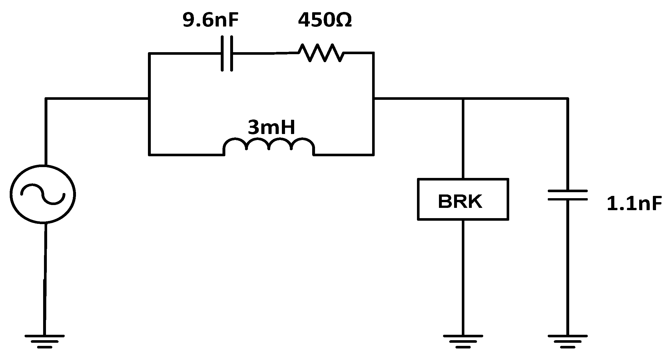
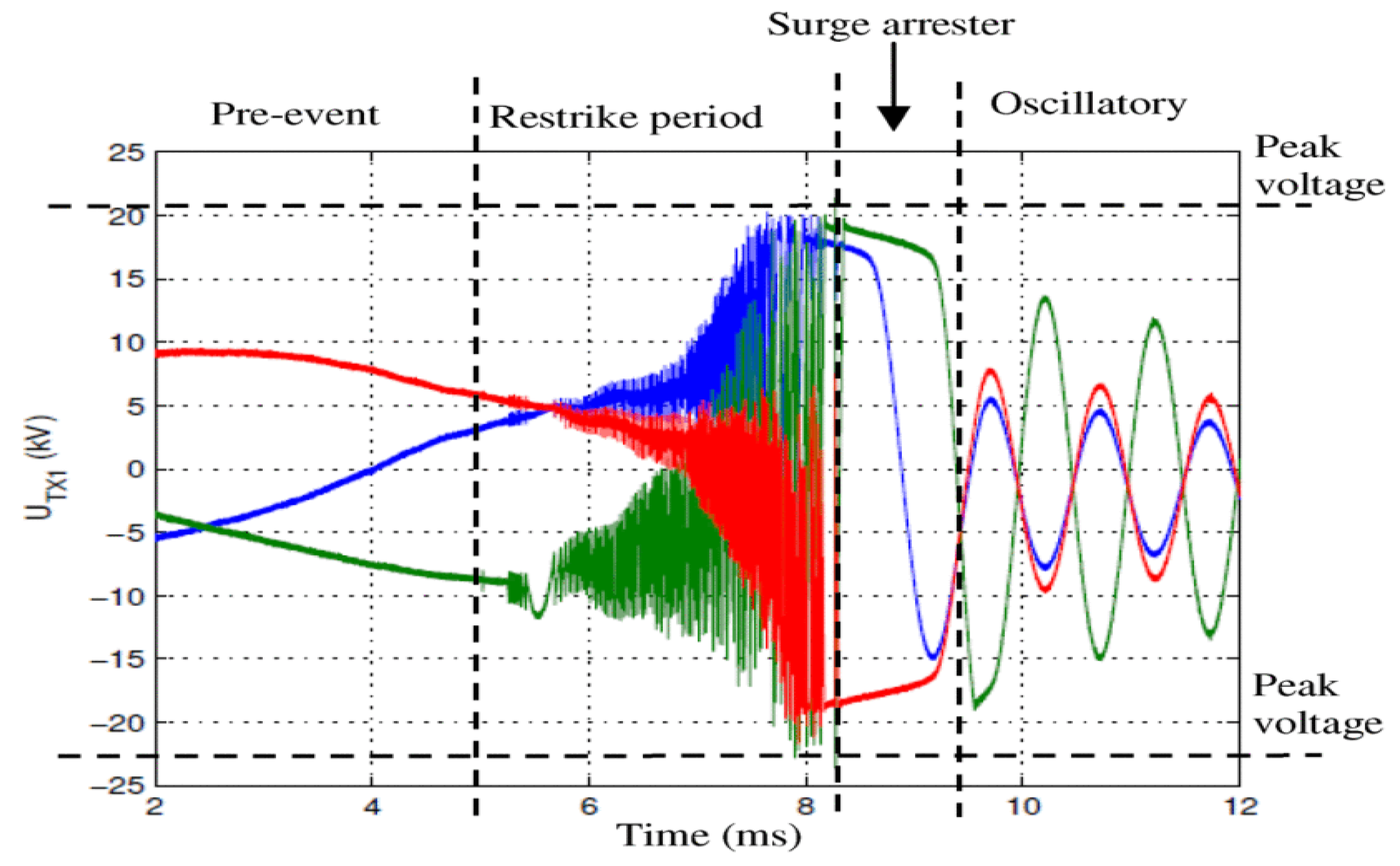
2.1.2. Circuit Breaker Transient Models

The SF 6 circuit breaker model, which was developed for the transient examination of WPPs, is composed of two resistors connected in series and integrates Cassie’s and Mayr’s dynamic arc models, as shown in Equation (9a,b) [34].
(1) Cassie’s transient model:
1 g c d g m d t = 1 τ c ( v 2 V 0 2 1 ) ,
where g c is the Cassie arc conductance, v is the arc voltage, τ c is the Cassie time constant and V 0 is the arc voltage coefficient.
(2) Mayr’s transient model:
1 g m d g m d t = 1 τ m ( v i P o 1 ) ,
where g m is the Mayr arc conductance, v is the arc voltage, i is the arc current, τ m is the Mayr time constant and P o represents the steady-state power losses (cooling power). PSCAD/EMTDC simulation case studies were implemented using the test circuit shown in Figure 6 to validate the merged models of Cassie and Mayr. The disruption of a short-line fault on a 130 -kV Sulphur hexafluoride (SF6) circuit breaker was simulated using a test setup [35].
In practice, nearly all transient overvoltages are normally deposited on the transformer and not on the machines [10]. The individual transient model components treated were the vacuum and SF 6 circuit breakers, three- and quadruple-core cables, turbine generators, power transformers and surge arresters.

3. Transient Analysis in WECS

An approach to analyse the complex transient trends and dynamic characteristics of a DFIG meticulously during a voltage dip was proposed in [36,37,38]; this work utilized a built-in DFIG model in which the effect of several prototype parameters and simplifications (for mechanical and electrical subsystems) on the DFIG-based wind power transient responses was demonstrated and investigated. The data furnished by the manufacturer were applied to the developed model to verify the steady-state operation, transient analysis and controller action through several simulation processes. The differences between the steady wind speed, wind power and mechanical torque of the DFIG were clearly shown. Transient studies, the theory of constant mechanical power or torque results of an imaginary response were established.
Transient analysis of a power system with increased DG penetration was studied in [39], the beneficial and detrimental impact associated with the increased penetration was observed to be dependent on the location of DG installation and the type. The penetration is characterized with phasing out of the existing traditional generators and the general effect on the system inertia.
The DFIG wind turbine model was introduced in [40], and the associated transient electromotive force (EMF) characteristics under grid fault conditions were derived. In a grid fault occurrence, the stator flux usually contains negative-sequence components and transients, which stimulate the large EMF in the rotor circuit. The DFIG equivalent circuit from the rotor side is presented in Figure 7.
Ignoring stator resistance x R s , EMF under normal conditions can be expressed as follows:
e r r = L m L s d d t ψ s r = L m L s s U S N e j S ω S t
where U S N is the rated stator voltage, ω s is the stator angular frequency, L m is the magnetizing inductance, L s is the stator self-inductance and s is the slip. Equation (10a) further indicates that when a transient fault occurs, the stator flux contains transient components that can be expressed as follows:
ψ s s = ( 1 p ) U s N j ω s e j ω s t + p U s N j ω s e t τ s ,
where p is the depth of the grid voltage dip, τ s = L s R s is the time constant of the stator flux, ψ s r and ψ s s are the stator fluxes and the superscripts r and s denote the rotor and stator reference frame.
Additionally, Reference [41] recommended removing the “missing” positive sequence part of the stator flux after conducting a uniform-speed transient evaluation of the overall stator flux and rotor EMF. The transient characteristics of a wind turbine mounted on a DFIG were studied in [42] through a generic approach, considering the applied voltages due to the RSC at the rotor windings during symmetrical voltage faults.
Conventional Fourier transform is ineffective and inaccurate in fault detection because the DFIG runs predominantly under a transient state, whereas Fourier transform is more indicative in harmonics analysis since the basic functions (the sines and cosines) waveforms are periodic in nature [43]. The basic method for exploiting the generator transient response during excitation was presented in [44]. The switching transient of a rotor-side inverter can usually develop a fault detection mechanism for sensing the fault generated by machine asymmetries and estimating the transient leakage inductance.
The authors in [45] addressed the transient stability and the out-of-step (OOS) event in the inverter interface synchronous generators (IISG). The distinction between the development of OOS in IISG and the conventional generators is expounded on the basis of the equal area criterion (EAC). Although, EAC was observed to be ineffectual in transient stability evaluation of power systems. The detrimental impact associated with the surge in the incursion of PMSG-based wind turbines on power system transient stability was investigated in [46], and using the extended equal area criterion theory (EEAC), the strong correlation between the power system transient stability and the PMSG integration was also determined.
A complete research on transient and dynamic behaviour of the DFIGs, working under balance and unbalanced grid voltage dips, was presented in [47]. The analysis also proved that the DC component generated in the magnetic flux is a result of sudden change in the stator voltage, which is thought to be a transient recovery.
The transient performance of a WPP was assessed in [48] to validate the restrike and prestrike operations of a vacuum circuit breaker (VCB) with a windmill switch gear, as shown in Figure 8. Case studies were simulated using the simulation software PSCAD/EMTDC.
The case study introduced in [48] from the General Swedish Electrical Limited Company (ASEA), analysed several features related to the transient characteristics of the collector grid, which include the following:
(1)
maximum voltage,
(2)
rate at which the voltage rises,
(3)
oscillation frequencies at each closing of the restrike or prestrike period,
(4)
breaker maximum current,
(5)
traveling time of the cables and
(6)
the relationship of the voltage to the current.
In all the cases, the operational time of the breaker was fine-tuned to obtain and match the equivalent points on the voltage waveform, as demonstrated in [49]. The measurement and simulation were qualitatively and quantitatively compared. Figure 9 illustrates a qualitative analysis example. The quantitative comparison measured the current voltage wave shapes and the timing of considerable occurrences by considering dU ,   dU / dt , peak voltage and the frequency of oscillations. Peak voltages dU ( Δ U ) and dU / dt were derived from the voltage wave form of the time domain during the prestrike or restrike periods.
A dynamic analysis of an improved transient model of a single-phase induction generator was introduced recently in [50] and fitted for renewable energy conversion. The Runge–Kutta technique was used to calculate the dynamic performance. Given the operational parameters and defined initial values, the nonlinear differential equations were solved using the ode45 function in MATLAB to obtain the system parameters.

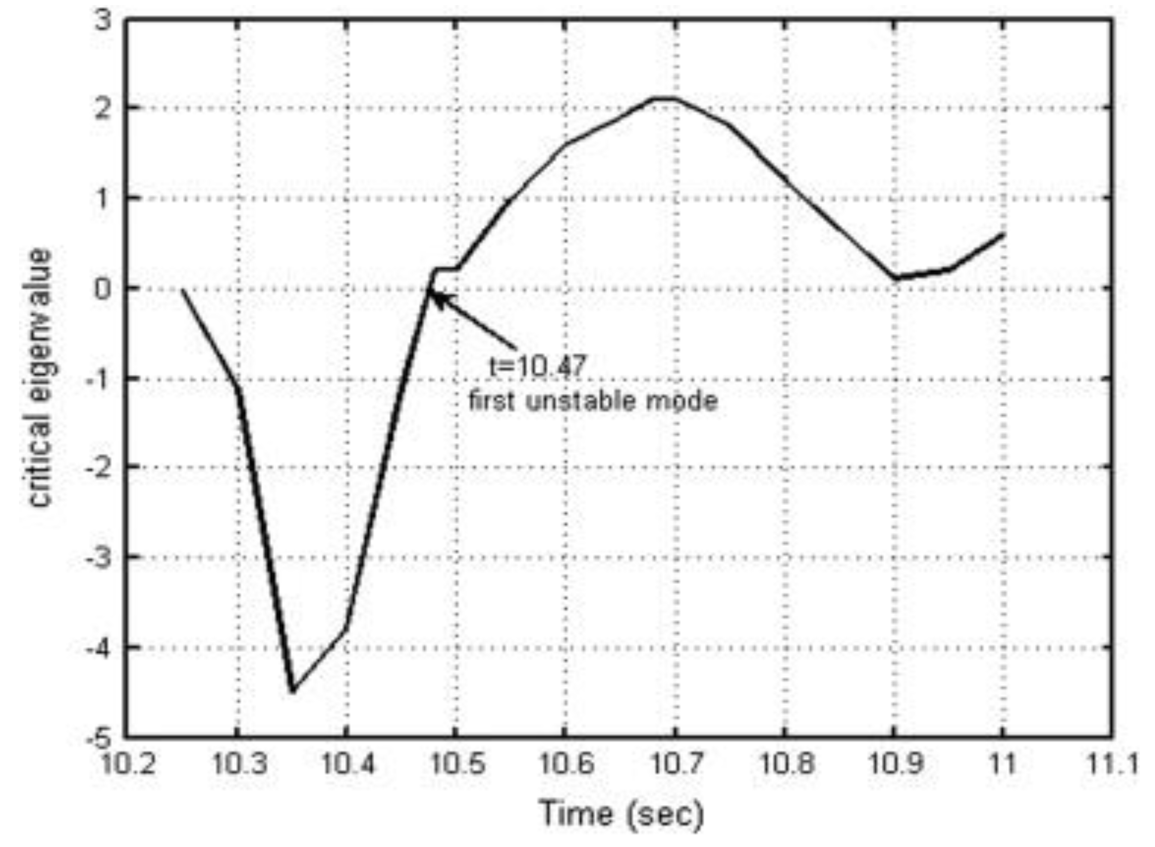
Transient Stability Analysis in WECS

TSI is widely used to assess the transient stability in a wind turbine employing the DFIG generators, after the occurrence of disturbance, during which the rotor angle of the machine with respect to a synchronously-rotating reference was used as a variable in evaluating system stability. The TSI was derived from the transient security assessment tool (TSAT), which computes the index according to the algorithm of the margin angle [6,51], as shown in the following:
T S I = 360 δ m a x 360 + δ m a x × 10 100 < T S I < 100 ,
where δ m a x is the maximum angle of departure between two generators, one working concurrently in the system and the other after the fault response. T S I 0 and T S I > 0 correspond to unstable and stable conditions, respectively.
A substantial number of wind turbine generators is expected to be integrated in existing utility grids in the coming years [52] Therefore, the transient stability of power systems that are distinctive from wind turbine generator systems (WTGS) should be studied [33]. Furthermore, a wind turbine system that consists of a one-mass or lumped model cannot be used to examine the transient behaviour of a WTGS because of the paucity of detailed technical information. For an accurate transient analysis of WTGSs, a six-mass drive train model is recommended. During its implementation, unequal torque distribution does not alter the transient stability of the WTGS, which provides an impetus to consider reduced-order three-mass and two-mass models. In the case of the transient stability of a WTGS, simulating every wind turbine is tedious. Therefore, a wind turbine with an equal torsional natural frequency is summarized as follows [53,54]:
J ɷ t = i = 1 P J ɷ t i ;   J g b = i = 1 P J g b i ;   J g = i = 1 P J g i ;   K = i = 1 P K i .
Each wind turbine number is denoted as i s ; P is the total number of wind turbines; J ɷ t , J g b and J g are the wind turbine, gearbox and generator inertial moments. For transient stability assessment, balanced three lines-to-ground faults (3LG) were deliberated. Several non-symmetrical faults, namely double line-to-ground fault (2LG, Lines a and b), double line-to-line fault (2LS, between Lines a and b) and single line-to-ground fault (1LG, Line a), were also studied. PSCAD/EMTDC was used to implement the simulation. Table 1 and Table 2 summarize the results by taking into account the damping on the one hand and ignoring it on the other, where S   and   U denote the steady and unsteady situations of the WTGS, respectively.
In all the cases, the two-mass shaft models provided similar transient responses as the three-mass and six-mass drive train models.
The operation and control of the fifth-order model of the DFIG wind turbine and the third-order representation were compared [55], during which the stator transients were ignored. For studies on power system transients, the addition of the generator stator transient and network transients increases the order of the general model of the system, thereby restricting the system dimension, which was to be simulated. Furthermore, a small-time increment is needed to perform the numerical integration, which results in increased computational time. Thus, stability studies of large power systems commonly reduce the order of the generator and ignore the transient of the network.
A hypothetical assessment of the dynamic and transient characteristics of fixed-speed wind turbine (FSWT), wind speed variations and severe voltage dips was demonstrated in [56,57]. Modal and sensitivity analyses were employed with the participating factors, and then, eigenvalue tracking was applied to classify and examine the behaviour of transient instability, together with the system variables involved in the trend of instability. To depict the FSWT’s transient performance, analysis was complemented with time simulation, and an eigenvalue tracking technique was implemented in [42,58,59]. In this technique, the system was iteratively linearized by the development of the state Jacobian matrix at specific time intervals during the simulation; the eigenvalues were calculated at each snapshot. The single-machine infinite bus (SMIB) system shown in Figure 10 was used to study the transient stability with FSWT parameters, where the system investigated the behaviour of transient stability. A balanced three-phase fault was foisted on the infinite bus terminal at 10   s for 200 ms.
The simulation result showed that the transient behaviour of the FSWT was unstable. Eigenvalue tracking and online linearization showed that all electrical modes remained stable after fault clearing, but the FSWT lost its equilibrium when the monotonic mechanical modes approached the unstable state. Figure 11 shows the critical eigenvalue as it developed in the considered instability case. The observed eigenvalue resembled a monotonic mode. The oscillatory mechanical mode is another critical mode and approaches instability under transient states. Figure 12 shows the damping of this mode after fault clearance [56].
The obtained result indicated that the multi-mass mechanical dynamics and single-mass model of the WT rotor were the governing kinetics for dynamic transient analysis in the FSWT. These factors were insufficient because their dynamic and transient investigation yielded misleading information about stability. However, from the transient stability perspective, the wind turbine drive train has to be modelled using two-mass representation to enable the simulation of the torsional oscillations initiated within the drive train system during grid fault [60].
A DFIG-based wind turbine model was designed in [61], using the time scale of the rotor speed control, to examine the transient response of the generator. The effect of the unique behaviour on the transient stability of the DFIG-controlled SMIB system was evaluated. To further appreciate the transient response and to test the stability of the DFIG-based WT, the magnitude and phase model of the DFIG-based WT is suggested from the internal voltage vector viewpoint and the application of the rotor speed control time scale. The transient energy function (TEF) of the SMIB system was employed to compare the transient stability of the DFIG-WT with the conventional synchronous generator (SG).

4. Transient Phenomena in HVDC and Offshore Wind Farms

Transient stability analysis determines the magnitude of the current and voltage under fault conditions and at fault event retrieval. The control schemes of the HVDC rectifier and WTG play a significant role in managing and directing the fault shape in offshore AC systems. HVDC and WTG converters are used to regulate their effect on fault current. Transient system evaluation requires a timescale of hundreds of microseconds to a few milliseconds from fault incidence to a few milliseconds after fault retrieval. Transient system assessment requires exact and sufficient models of HVDC converters, wind turbine generators, necessary control schemes and passive components, such as transformers and cables in positive, negative and zero sequences. In the design of HVDC converters, manufacturers use an electromagnetic transient (EMT) simulation software to create a representation of HVDC converters. Then, the system characteristics are validated using dynamic simulations in the time domain [62].
The voltage source converters (VSC) employed in HVDC transmission systems are mostly controlled to ensure transient decoupling and halt instability transmission among intercoupled systems. However, this process blocks the essential support in transient events, which is provided by system inertia [63]. A strategy for controlling voltage source converters in multi-terminal direct current (VSC-MTDC) in offshore wind farms using the static voltage-current behaviour of the inverter and rectifier was proposed in [28] and demonstrated an increase in the stability of an HVDC network with the proposed scheme during exposure to transient faults. A transient stability evaluation of an offshore wind farm with a PMSG was conducted in [45]; the mechanism was linked to a grid located at shores via the HVAC or through the HVDC transmission system equipped with a VSC.
The significantly complex task from the elaborate modelling of modular multilevel converter MMC-HVDC systems in EMT-type programs complicates the simulation of transients when such systems are attached to large networks. To model this type of converter topology in an EMT-type simulation tool, MMC must face various challenges due to a large number of switches [64]. The topology in [65] demonstrated the accuracy of estimating the model of an offshore wind farm, including its efficiency, with multi-terminal HVDC connections that are based on MMC.
The switching overvoltage of a power grid arrangement that consists of VCB, submarine cables, and transformers, which are peculiar to offshore wind farms were investigated in [66]. The negative effects of prestrike in VCB should be identified to study the switching transient overvoltage. One of the severe stresses in an offshore wind farm is caused by switching transient overvoltage, which is usually instigated by the scheduled energizing or de-energizing actions of plant components and fault-clearing operations that depend on the response of protective relays.

HVDC Transient Protection and Improvement Scheme

The transient and steady-state performance enhancement of HVDC schemes has long been an intriguing area of research in academia and industry, especially in the field of offshore transmission systems. A strategy for enhancing the operation of offshore wind farms with the use of HVDC power transmission was demonstrated in [7].
An innovative transient energy protection scheme was propounded in [67] on the basis of steady-state transmission-line equations, and the parameters for the distribution of the DC line were also considered. The incremental transient energy in the DC line was applied to pinpoint the internal and external faults. The basic structural diagram of a standard HVDC transmission system is depicted in Figure 13. The DC transmission-line protection components are retrofitted on either end of the line, M or N. i M , i N and u M , u N are the dc currents and voltages, respectively. The abovementioned electrical quantities and their positive directions are illustrated in the diagram.
The transient energy from t 1 to t 2 at the measuring point can be deduced using Equation (12).
{ E M = t 1 t 2 P m ( t ) dt E N = t 1 t 2 P n ( t ) dt
The incremental transient energy is expressed as Equation (13).
{ Δ E M = t 1 t 2 Δ P m ( t ) dt Δ E N = t 1 t 2 Δ P n ( t ) dt
where P m ( t ) and P n ( t ) are the powers immediately measured at two points, M and N , and Δ P m ( t ) and Δ P n ( t ) are their increments, respectively. When continuous time t 1   to   t 2 is substituted by n . Δ t , (y) can be transformed into discrete time, as expressed in Equation (13), where n is the time index and Δ t is the interval of sampling. In addition, the small increments in DC voltage and the currents at points M and N are designated as Δ u M , Δ i M , Δ u N ,   and   Δ i N . Thus, the incremental transient energy can be obtained using Equation (14):
{ Δ E M = i = 1 n Δ u M i Δ i M i Δ t Δ E N = i = 1 n Δ u N i Δ i N i Δ t
Therefore, the increment in transient energy of the DC line is expressed as Equation (15).
Δ E = Δ E M Δ E N
Under steady-state operation, Δ E M = Δ E N = 0 and Δ E = 0 . When fault occurs, the abovementioned relation is rational if the transmission line from M to N is ideal. However, contemporary HVDC transmission networks have an extended span and large capacities.
The distributed parameters may result in the malfunction of protective relays. The transient harmonic protection procedure based on the formulation of setting the values in Equations (16) and (17) was derived in [68].
I H . s e t = k i n t × k l i n e × k f a u l t . r × I H . i n t ,
N n . s e t = N n . i n t ,
where k i n t is the correction coefficient with respect to the change of I H . i n t ; k l i n e is the correction coefficient with respect to the transmission line length; k f a u l t . r is the correction coefficient in terms of fault resistance; I H . i n t is the transient harmonic current initial value; I H . s e t is the setting value of transient harmonic current; and N n . i n t is the initial harmonic pulse number in a single cycle, n = 12, 24, 36. In this condition, n = 12. N n . s e t is the transient harmonic current protection setting value for the harmonic pulse number in a single cycle.
I H . M = k 12 × I 12 . M + k 24 × I 24 . M + k 36 × I 36 . M ,
where I H . M is the measured transient harmonic current; k 12 ,   k 24   and   k 36 are the coefficients for the correction of harmonic current characteristics; and I 12 . M ,   I 24 . M   and   I 36 . M are the measured values of the 12th, 24th and 36th harmonic current characteristics. I H . M > I H . s e t indicates a faulty system operation, and the transient harmonic current protection should be notified. The condition represented in (19)
{ I H . M > I H . s e t N n . M > N n . s e t
implies an internal fault in the HVDC transmission line, and the transient harmonic current protection is nearly tripped instantly. The transient harmonic current protection test system was modelled on the basis of the International Council on Large Electric System (CIGRE) benchmark with PSCAD in [69,70].
Coupling a wind turbine generator to a grid involves the synchronization of the mechanical dynamics of rotating wind turbines and the electrical dynamics of the generator to that of the utility grid. Transient overvoltage degenerates the electrical power quality mainly because of the interaction of different equipment in power plants, especially WPPs, which comprise special components that are not commonly available in traditional power plants.
The change in topology triggered by equipment switching events causes transient faults induced by short circuit current, which consequently establishes resonant conditions in a power plant. However, wind farms that employ fixed speed induction generator (FSIG) coupled to HVDC lines and are equipped with line-commutated converters are quickly becoming popular in the transmission of large amounts of electrical power over long distances with significant reductions in transient instabilities, especially due to sub-synchronous torsional interaction [71,72]. Recently, a novel technique for detecting several DC fault conditions in a multi-terminal VSC-HVDC scheme was devised in [73] with the use of transient overvoltage with respect to the cable sheath.
Travelling wave fault locators (TWFL) presented in [74] were implemented to locate faults, in the HVDC transmission line system. The location technique involves the exact measurement of the time taken when the travelling waves (produced by the wave fronts as a result of transient due to the occurrence of phase faults) is propagated along the measurement points, most often the substation situated at the transmission line ends.

5. Methods for Mitigation and Control of Transients in Wind Turbine Generators

The possibility of damping transients within the power system utility under any disturbance, such as voltage fluctuations, was indicated in [75]. WTG operations are nearly transient, and a nonstationary method should be applied to recognize faults. A secondary damping controller was embedded in the primary controller of a DFIG for the damping oscillations in the system that result from the rotor oscillations of the generator in various areas [19]. The sole purpose of the controller was to ensure the suppression of new oscillation modes that might be introduced by the DFIG using a wide area measurement system. The damping control scheme was executed in the software presented in [65].
Power system dynamics are not considered obstacles in increasing the penetration of wind energy, although wind turbines significantly distort the transient and small signal dynamics of power systems. Given the existence of wind turbines with constant speeds, precautionary steps must be implemented to avert voltage and rotor speed instability and thereby achieve transient stability [76].
The static compensator (STATCOM) is a member of the family of flexible AC transmission system devices, which have been adopted successfully in WPPs to boost transient voltage and thus protect systems from failure [54,77,78]. The major aim of coupling STATCOM to a wind farm is to mitigate the transient stability and to offer fault ride-through capability of the system [79]. Although flexible alternating current transmission system (FACTS) are becoming obsolete, STATCOMs are increasingly applied, especially at the distribution level.
A control approach that uses STATCOM for reducing and suppressing distortions in a power system was implemented in [37]; the method offered substantial improvement in the transient stability margin of a wind park. The latest application of the STATCOM-based mitigation method was introduced in [80] by proposing a model reference adaptive controller (MRAC) for facilitating the addition of WECS, when the working condition of the grid was characterized with anomaly and taking into account the low-voltage ride-through (LVRT). The principal objective is to manage the flow of volt-amperes reactive (VAR) between the grid and the STATCOM, by adjusting the firing angle of the sinusoidal pulse width modulation (SPWM). This was achieved by forcing the voltage at PCC to track the predetermined voltage.

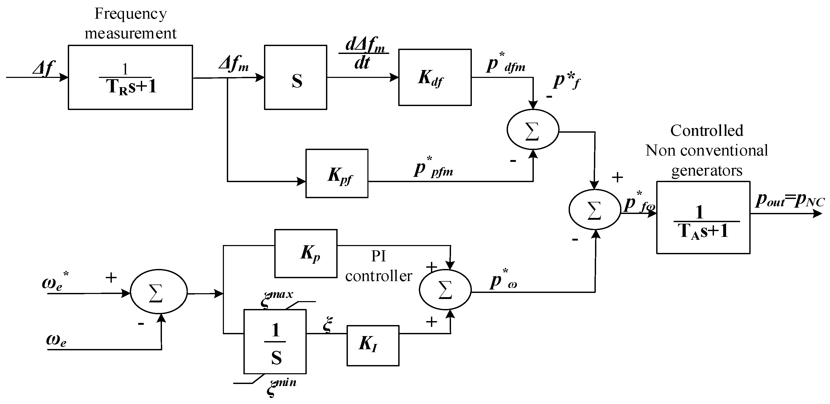
5.1. Transient Control Techniques in WECS

A feed-forward transient compensation (FFTC) control system with a proportional-integral-resonant regulator was introduced in [81], and various remedies to satisfy low-voltage ride-through conditions were adopted by implementing the control techniques for RSC. Some of these techniques focus on enhancing the transient response of the control scheme with an equal reference current in the rotor as a typical vector control. For example, FFTC control methods were used to limit transient rotor currents. Transient mitigation terms and parameters are applied on the current, power and input of feed-forward control loops to facilitate transient current control.
The proposed FFTC control framework is depicted in Figure 14 in which two functional blocks are inserted in the conventional vector control scheme. d and q transient rotors and back EMF voltages were feed-forward-compensated in the planned FFTC control system. Therefore, the small slowly-varying error in the PLL angle that only affected the decomposition of d-q did not reduce the transient responses. In the study, PLL was designed to block the negative sequence components.
By contrast, [82] reported that the feed-forward power signal from an induction generator via the DC voltage loop inhibited the transient spikes of the link voltage. The relationship between the maximum power point-tracking (MPPT) speed and the transient load of a direct-drive PMSG-based variable-speed wind turbine was investigated in [83]; the higher the MPPT speed, the larger the ripple (produced by the torque and described as transient load) the turbine shaft could receive. The previously mentioned contribution showed that the usual difficulty encountered in settling the transient load and MPPT speed can be resolved by enhancing the bandwidth of the MPPT control scheme, which is shown in Figure 15.
The application of the closed-loop transfer function by shaft torque in terms of rotor speed is an appropriate method for expressing real transient load. Thus, Equation (20), which is derived from the equivalent circuit, can be considered a representation of the real transient load. This equation depicts the effect on real transient load.
| δ P d c δ ɷ   Q | = J ɷ Q = J λ o p t l n ε R K 0 . 1 T ε + J λ o p t K 1 R K 0
In addition, the connection between MPPT speed and the transient load acting on the turbine shaft is described using Equation (20), where λ o p t is the optimal tip speed value of the wind turbine; J is the overall moment of inertia of the scheme in ( kg / m 2 ) ; P d c is the power generated by WECS in watts; ω is the rotor speed; Q is the steady state point, where ε = Δ P ϵ 2 | Δ P 0 | and Δ P 0 = 3 , ε = 5 % ; R is the radius of the turbine in meters; T ε is the time for convergence in seconds; T ε = 1 A ln ( ε ) and K 1 = K ω 2 JR S K t α 0 R 2 J λ opt 2 , where α 0 = 0.312 ; and K 0 is a constant.
A predictive torque control (PTC) was applied in [84] to achieve very fast transient responses in a brushless doubly-fed induction generator (BDFIG) with a matrix converter. The PTC approach for the combination of BDFIG and the matrix converter was proposed due to its advantage of yielding high power density and being robust to mechanical associated faults. A bridge-type fault current limiter (BFCL) was recently introduced in [85] for boosting the resistance of the PMSG employed in bulk wind power generation to fault occurrence, while undertaking loads. In another case, the power hardware in the loop (PHIL) trial was performed in [86] to examine the transient characteristics in case of fault occurrence prior to the fault current limiter (FCL), with regard to the DFIG system. The study of fault current of Type-3 WTs was carried out in [87] to estimate the transient and steady-state equivalent circuits of Type-3 WT by taking in to account the switching sequence of the internal circuits for protection and control in multiple time scales, during LVRT.
Another robust control scheme for a dual three-phase PMSG was adopted in [88] by introducing a speed controller that commands the generator to operate at the maximum speed, but with the least amount of transients under various wind speed conditions. It was demonstrated in [89] that passivity-based linear feedback control (PBLFC) enhances the transient responses of PMSG-based WECS. Linear feedback control was applied to ensure the required convergence of error tracking. However, It has been observed in [90] that during transient fault in PMSG, the orientation of the phase angle cannot precisely track the angle of the voltage vector. Therefore, better synchronization and reactive power support are required for low-voltage ride-through (LVRT).
An adaptive controller for WECS with undetermined system dynamics was proposed in [91], in which transient stability and the steady state were achieved after quantitative examination. The controllers could outline the tracking errors by employing novel error transformation methods to ensure subjective transient and steady-state operation, including steady-state error, convergence rate and maximum overshoot. The wind speed approximation based on a sensor-less control system controlled the WTG under large transient disturbances efficiently and precisely.
A fault-tolerant controller for WECS was designed and developed in [92], using the sliding mode observer (SMO) and by the application of the multiple fault reconstruction technique. The issue of the fault-tolerant controller arises usually when several faults (transients) are observed in WECS. The state equation was deduced and the new streamlined scheme was built based on the orthogonal transformation matrix and post filter, after which the sensor fault would then be transformed into the actuator fault to diagnose. Another robust adaptive fault-tolerant control methodology was realized in [51] based on the application of the barrier Lyapunov function to trace the required power signal of each wind turbine with assurance in its transient performance and high immunity to the actuator faults.
A supervisory controller for developing resistance to fault, owing to lubrication breakdown in the gearbox mechanism of a wind energy system, was composed in [93]. This control formulation maintains the output power of the wind scheme, at its assumed value, and prevents potential converter failure. In a similar case, an effective fault detection mechanism, in a wind energy system to address the issue of lubricant system failure, was developed in [94]. A faulty lubrication system has a negative impact on the transmission efficiency of the gear box and, consequently, could upset the transient stability of the system.
The rotation of the wind turbine in a system under transient fault was analysed, in the latest issued grid connection requirement of the Norwegian power system, as wind turbines are required to withstand transient faults. This process should be implemented to avoid substantial generation loss under harmless transient faults. Otherwise, this grid codes should be followed [95].
Variable-band vector-based hysteresis current regulators (VBHCR) were developed in [96] to overcome the limitations of several current regulators, such as the sluggish transient response of proportional integral (PI) current regulators, which adversely affects the immunity of DFIGs in the event of fault. To tackle the shortcomings of PI current regulators, RSC and grid side converter (GSC) were substituted with VBHCR to meet the newly-issued Australian Grid Code requirements for the transient response of large WPPs. The working conditions and execution of this current regulator in a DFIG-based WPP were thoroughly studied in [97]. Results from an extensive simulation were also presented, indicating the remarkable transient and steady-state performance of the suggested VBHCR under various regular and fault working conditions.
A schematic representation and realization of the suggested VBHCR in the RSC of DFIG is shown in Figure 16. For this current regulator, the tracking errors of the x- and y-components were treated by four- and three-level hysteresis comparators, respectively. D x and D y are the digital outputs that are fed to an uncomplicated switching table that decides the RSC output voltage vector at each instant. The proposed current regulator has built-in current-limiting characteristics and rapid transient responses [98]. A somewhat similar approach was implemented in [44] using the genetic algorithm with PMSG.
A control technique for the improvement of transient stability in a system of wind energy employing DFIG was reported in [99] by exploiting the power constraints of the generator. As observed in WECS, the GSC most often runs on the course of the unity power factor and delivers reactive power during the reactive power, when the orientation of the d-axis is tilting towards the grid voltage as the RSC. The transient power of GSC is expressed in Equation (21).
{ P D g = U D s i D g d Q D g = U D s i D g q
where i D g d is the d-axis reference of the grid current, i D g q is the q-axis references of the grid current and U D s is the magnitude of the stator voltage. The active power from the rotor side drifted to the GSC, then the rotor active power would be equal to the grid active power, that is P D r = P D g , neglecting the loses in the rotor and stator. The references were applied to manage the transient currents of the DFIG.
A transient primary regulation technique was presented in [9]; the proposed technique, which depends on traditional primary regulation, was adopted in the transient approach. The result from the designed controller was used as a surplus power reference to be tracked by an analogous special generator-type controller. Thus, the reference signal is expressed as Equation (22). In addition, inertial transient control was introduced after the analogous special generator recovered the maximum speed when the frequency transient decayed. Figure 17 represents the inertial transient control. Furthermore, in the latest advancement, the synthetic inertial control method for the DFIG, introduced in [100], lithium-ion supercapacitors were utilised to strengthen the DC bus in in the event of transient and to upgrade its transient/fault ride-through capability.
Insulated-gate bipolar transistor (IGBT) switching transients, which are based on device characteristic models, were examined in [101]. A common behavioural methodology for representing the turn-on and turn-off dynamics was studied in [102]. A faster and effective control approach in a WECS, employing a full-bridge inverter, was proposed in [103] and was observed to enhance the transient and steady-state performance. The proposed control strategy comprises the sliding-mode guidance law (SMGL) and a Fourier nonlinear grey Bernoulli model (FNGBM). In [104], a control method based on fuzzy PI was implemented for controlling the IGBT to facilitate transient stability. The efficiency of a “transistor-based frequency converter employing a reduced order control system” was validated in [105], by the use of original transient switches, that is trimming the total number of power supplies in the control scheme.
p f = 1 R Δ f m
where R is the usual droop constant applied and parameter Δ f m is measured in relation to the frequency in the interconnected bus between the special generators and the remaining part of the power system. The researchers in [106] discovered that the DFIG regulation capacity of active power is usually uncertain because it strongly depends on its low-voltage ride-through capacity. Thus, a DFIG retrofitted with a super conducting magnetic energy storage has been recommended for voltage frequency support.
In this application, the power reference that enables the speed to track the required speed reference is calculated using Equation (23).
p ω = k p ( ω e ω c ) + KI ( ω e ω c ) dt ,
where ω c is the rotational speed, ω e denotes the reference speed, p ω represents the reference power and K p   and   K I are the model constants for the PI controller that must be used to achieve the following:
  • fast recovery
  • speed variation of the transient for a limited period that enables a special type of generator to inject the required amount of active power to remedy the transient frequency deviations.
In other words, the surplus power supplied by the nonconventional/special machine throughout the frequency transient was gained from the stored energy within the inertia of rotating masses analogous to WECS. A recent advancement in [107] was presented to expedite the inertial regulation when frequency perturbation occurs by implementing an extended system frequency response.
Different types of controllers were studied in [108] to determine the best in terms of improving the transient stability of DFIGs in the event of large grid distortions. Recently, an adaptive neuro-fuzzy-controlled flywheel storage scheme was studied to facilitate the transient stability in grid-tied wind farms further [73]. Although, a hybrid controller employing both PI and a fuzzy logic controllers (FLC) introduced in [109] was seen to provide a more coherent technique to carry out transient stability on SCIG and has the advantage of requiring no extra equipment.

5.2. Transient Protection Techniques on WECS

The modern topology of power electronics for wind turbines was investigated in [1], where connecting the induction generators to short-lived power system-generated transients with high inrush current was learned. This condition upset the grid and caused high torque spikes in the drive train of the wind turbine, which was directly connected to the induction generator, and restricted the permissible number of wind turbines to be installed due to the level of transient disturbances introduced in the grid. Mechanical switch capacitors (MSC) are among the effective mitigation methods of transient and steady-state voltage control. MSCs are composed of a bank of shunt capacitors that are mechanically switched to supply reactive power compensation. The volume of each capacitor should be down-sized to prevent large transients of voltage.
The transient process of a WECS that simultaneously operates as a power generator and an active filter (AF) was explained in [110]. The research was put forward to resolve the system response to two types of transient phenomena: wind variations (slow transients) and voltage dips (fast transients). The transient response of a WECS that executes the function of an AF operation under voltage dips or wind speed variations was investigated. The result of the experiment conducted on a DFIG system, as shown in Figure 18, was regarded as the first step to studying the transient response of a WECS when employed as an AF. The system under investigation is presented in Figure 18. The stator terminals of the DFIG are coupled with the PCC via a feeder, which was modelled as equivalent resistance R C and inductance L C .
Induction generators driven by wind are frequently exposed to power system transients during their working. Impulsive mechanical input power, which is mostly due to wind gusts, is considered one of the frequent occurrences of transients. This abrupt shift in input power can be represented as an incremental step in the input power. Voltage sag and short circuit are two common transients to which DFIG is susceptible. The transients of a DFIG due to external short circuit faults were evaluated in [111]. Voltage sag usually occurs due to short circuit in a remote bus or other generator terminals in a wind farm. The generator transient performance under the aforementioned conditions should be exactly forecasted for the appropriate selection, modelling and coordination of protective devices and for stability analysis [112].
The authors in [113] surveyed the behaviour of the short-circuit fault of voltage source converter-based DC distribution systems, with various dispersed generators. It was observed that, in the event of short-circuit fault, the bidirectional DC/DC converter and the DC link capacitors discharges a high transient current. The assessment was carried out by taking the three-phase short circuit measurement of the PMSG. For the ease of calculation, the d-axis sub-transient reactance was assumed equal to the q-axis sub-transient reactance, viz. X d = X q . In another case, the similarity of transient current was applied in [114] to formulate a protection scheme in wind farm transmission lines and also applied the indices of the correlation coefficient to compare the signals of the transient current on either end of the line span.
The applications of digital signal processing for detecting and diagnosing transient faults, in electrical power and renewable energy systems, was presented in [115] using local mean decomposition and in [116] using the Morlet wavelet. However, Morlet wavelets finds application in sensing high-impedance fault (HIF) during transient disturbance and to discriminate (HIF) from ordinary switching transient due to non-fault events [117]. Artificial intelligence-based relays such as the ANN and fuzzy logic systems proposed in [118,119], respectively, for the interconnection of distributed generations, suffer the requirements of trained data and a great deal of calculation, which are considered as drawbacks for their online implementation.
The wavelet transform breaks down the signal into only the low-pass components that constitute the approximations of the signal transform, while the wavelet packet transform (WPT) breaks down the transient signal into both the low-and high-pass components, which constitute the details of the signal transform [120]. The most efficacious diagnostic method in digital protection was discovered on the basis of sensing and categorizing the transient disruption that frequently occurs in distributed generation units (DGUs), that is the application of the phaselet packet transform, which was established and proposed in [121,122]. The method developed for sensing and categorizing transient disruptions determined the phases and magnitudes of the high-frequency content of the sub-band components presented in the d-q axis of the PCC currents.
A novel strategy for fault diagnostic and isolation (FDI) for wind turbines was introduces in [123], using the deep long short-term memory (DLSTM), and the planned technique was observed to possess superior diagnostic performance, when compared with the conventional wind turbine FDI techniques. The DLSTM was implemented on the basis of the data-driven residual-based approach. This method can be applied to all types of wind turbines. In [124], three-channel filters were designed to tackle the difficulties encountered in FDI for the redundant inertial measurement unit. The presumed concept offered the ideal situation to facilitate the operation of the FDI system. This can find potential application in the aerodynamics of wind turbines.
A schematic of the laboratory configuration of a permanent magnet generator (PMG-based WECS) is depicted in Figure 19. The PCC current components of the d-q axis (adopted by the principal controller of each DGU) were applied on the inputs of the phaselet frame-based digital protection, and the output was a trip signal that retained a voltage of approximately 10 V in non-fault events. The trip signal was derived via a three-conduit optocoupler driver circuit before it was guided through three triac switches [125]. Another transient signal detection technique that uses wavelet packet transforms in fault diagnosis using an induction generator was presented in [111].
Some faults initiate high-frequency components in which transient phases generate nonzero output in one or more high-pass filters. A fault on opposite sides of the PCC can be sensed and classified as fault and non-fault events denoted by the relation in (24).
D d q [ f ] = {   0 Nonfault τ Fault ,
where r R ( τ 0 ) , and vector D d q [ f ] is defined by Equation (25) as follows:
D d q [ f ] = D 0 [ f ] + D 1 [ f ] + D 2 [ f ] + D 3 [ f ] + D 4 [ f ] + D 5 [ f ]
Another recent advancement in transient fault detection and diagnosis was introduced in [106] by applying a space vector-based index in a wound-rotor induction machine. The diagnosis was achieved by extracting signature information obtained from the product of the rotor current and rotor voltage space vectors, termed as diagnostic space vector D ¯ SV , which is a tool for diagnosing the rotor electrical fault operating under transient speed.

5.3. Transient Protection of Wind Turbine Blade from Lightning

An approximate transient current wave-shape was deduced in [126] by using the double exponential function shown in Equation (26) in designing a fibre optic sensor network for localizing the effect of thunderstorm lightning and classifying wind turbines. In addition, a case study of transient current, as a result of the lightning impact on a wind turbine blade, was presented in [127].
i ( t ) = { 0 I p e a k ( e t t 0 τ 1 e t t 0 τ 2 )
The preceding function was derived using the simulation program Method of Moments (MoM), as previously defined in the transient current simulation. However, [128] mentioned that this function was incoherent with its first derivative at t = 0 . The MoM simulation technique failed to achieve transient current impulses. However, sinusoidal waves of various frequencies were applied to obtain the near-field and resonant effects in the structure and the blades. The power electronic topologies employed for disperse generations and ranging from 600   kW   to   2.75   MW were studied in [129], where the researchers observed that the transient rotor speed was permitted to increase up to 10% of the rated value during the survey on several wind turbines that were fitted with fibre optic systems.

6. Discussion

Exploiting electrical energy from the wind requires WTG and power electronic converters. Considering the intermittency of wind speed, the generator output power is represented in varying AC waveforms. Thus, the power fluctuates due to the disturbances introduced in the wind power systems, such as the sudden change in input mechanical power owing to wind gusts. This condition is often referred to as a transient fault. Among the power qualities in wind energy, the transient is the dominant one especially when DFIG is employed in the scheme.
The transients that originate from wind generators contribute to the oscillatory variations in active power and result in leakage and rotor flux saturation, which affect the transient performance of DFIGs and the step change in input power and cause short-circuit faults and voltage sags at the terminals of generators. The rotor current in p.u. is usually comparable to the stator current during the transient. Induction generators generally cannot withstand the considerable fault currents at their terminals for a long duration throughout the fault event due to failed excitation. However, they still transiently inject a high proportion of currents, which can adversely affect the power system.
Transforming the rotor and stator of the generator into an equivalent electrical circuit model is a common practice during the transient analysis of WTG, such as DFIG, to examine their transient characteristics. Any alterations in the circuit condition due to external disturbances, such as short-circuit faults, cause a transient readjustment of voltages and currents from the initial equilibrium state to the final equilibrium state. The instantaneous condition at the first instant of disturbance (time zero) is designated as the initial condition and is usually expressed using Equation (27) (as follows):
( Initial   Condition ) = ( Final   Condition ) + ( Transient   terms   when   t   is   zero ) .
The penetration of DFIG-based WTG in the utility grid is limited by network transients because it complicates and increases the order of the general model of the system, restricts the size of the scheme and increases computational burden. Therefore, a third-order machine model should be adopted for transient stability analysis because the simplification of the generator model does not significantly alter the DFIG transient response of DFIG. WECS simulation for transient stability analysis in the power system is performed by using the EMT program PSCAD/EMTDC. Table 3 summarizes a number of analysis and modelling methodologies.
In most of the transients evaluated, it has been observed that the prime cause of the dynamic response of the DFIG to a transient of grid voltage is the DC (natural) part of stator flux linkage constituents, and it is the transient factor that is attached to the stator. Apparently, as the magnetic field is continuous, no discontinuity was seen in the state variable of the generator. Moreover, a transient recovery is often regarded as a sudden alteration in the stator voltage, which then introduces a DC component in the magnetic flux. On the other hand, DC-link capacitance of inverters is an instrumental factor, in controlling and managing the transient stability of inverter interface generators.
Wind farms that are founded on VSC-HVDC and employing SCIG are often immune to grid fluctuations. This is because VSC-HVDC has the capability of facilitating the inhibition of power system transient faults, as a result of which, the generators that are weak in the event of power system faults such as SCIG and the DFIG can now be employed without the problem of fault ride-through (FRT) in the power system. The HVDC are commonly employed in long distance applications, as in transporting electrical power from offshore wind farms to the substations located on the land.
Transient events are experienced during the starting and braking periods of wind turbines. Thus, manufacturers of wind turbines frequently provide soft starter systems to reduce transient currents during the starting period, and such devices generally operate effectively. In several experiments [38], the shaft dynamics caused the active power to fluctuate and significantly affect the transient recovery of DFIGs, depending on shaft stiffness. The inertia encountered in WECS from the blades and the generator mostly altered the control of power intake at high wind velocity and introduced transient torque in the generator, which affected the quality of the electrical power injected in the grid by introducing grid frequency instabilities that have higher frequency deviations from the nominal 50 or 60 Hz. Table 4 summarizes various remedy approached in wind energy technology. In PMSG schemes, there is no transient power-angle features as in the typical synchronous generator or any inertial tendencies manifested toward the grid, i.e., inertia remains constant.
The operation of DFIG was found to be dominated by transients; therefore, traditional Fourier transform was ineffective in identifying faults involving transients [44]. The most accurate technique was discussed in [121]. Therefore, Fourier transforms are more indicative than transients in faults involving harmonics. (1) The FFTC technique supplements the voltage dip owing to the grid reactive power consumption by the loads [81]; (2) The fault indicator that specifically points at the faulty phase and isolates it is obtained by rotor-side transient current measurement [44]; (3) The application of the wavelet packet or phaselet transform to accurately diagnose whether the transient is related to the fault or not [121] can substantially reduce the downtime of a DFIG-based system when integrated into a single control entity. Appendix A enlists the simulation parameters of the DFIG that would be used.

7. Conclusions and Predictive Validity of Research

A comprehensive review of the transient phenomena that evolve from the applications of wind energy technology is elaborated in this paper. The equations and techniques used in the analysis of transients due to the rotating parts of WTG and those of the protection of HVDC converters are introduced. Additionally, models of transients that originate from the stators and rotors of WTGs are discussed. Furthermore, various control and protection systems that are used in the remedy and mitigation of transients are clarified. Future research for transient control in WECSs, which utilize DFIGs, should design and implement an improved version of a crowbar or the so-called digital crowbar that incorporates additional features to protect the RSC and effectively manage the high inrush of transient current, which may induce voltage oscillations in the grid. Digital crowbar implementation involves the application of the phaselet transform and overcurrent digital relays that specifically classify a transient, which is related to a fault or non-fault event, before precisely tripping the affected phase.
The digitization of protection and control systems for wind energy technology during the integration to an existing utility will enable plug-and-play operations in renewable energy harnessing and applications. Plug-and-play is a terminology used in computer science, in which the software and hardware operate together automatically to allocate resources. This permits hardware adaption and incorporation of new ones, with insignificant or noticeable adjustments. The objective is to have the means of plugging in an external device and using it instantly, with no substantial alteration in the original configuration of the system. The above-mentioned feature is essential in the future of wind microturbines, which are expected to play an assisting role and participate in the assigning of resources. The hardware is analogous to the wind turbines, power electronics interface, generators and the loads, whereas the software is analogous to the digital signal processors (DSP) or field-programmable gate array (FPGA).
In summary power quality is fundamentally related to the variations in magnitude and voltage or current wave shape, and this precipitates into a number of technical problems, as a consequence of integrating an external source with an existing utility grid; this includes harmonics, transients, flickers, dips and swells. Transients and harmonics are the two common sources of bad power quality in WECS, in standalone or grid-tied systems. Most of the control and protection techniques employed are streamlined towards achieving transient stability or harmonics cancellations. In addition to that, the variable speed wind WTG are quickly replacing the fixed speed generators, because the former are more compatible with many control systems and less susceptible to grid voltage fluctuations, while the latter are gradually being phased out from the market along with their subsequent decommissioning from many wind farms. In a similar development, variable speed (DFIG and synchronous generator) can be embedded with frequency response into the turbine control scheme using a software upgrade, but the FSIGs are found not to possess this characteristic.

Author Contributions

This work was initiated, written and put together by U.A., under the full guidance of S.M. and H.M. More technical inputs and suggestions was offered by M.S. The language was checked by B.H. and A.S. and further assisted with more relevant information while H.B. and M.J.H.R. made the critical and final reviewing of the manuscript.

Funding

The authors would like to acknowledge the financial support received from the University of Malaya, Malaysia, through Frontier Research Grant No. FG007-17AFR and Postgraduate Research Grant (PPP) No. PG192-2015B.

Conflicts of Interest

The authors proclaim no conflict of interest.

Appendix A

Simulation Parameters of the DFIG
Rated Power4 kW
Stator resistance R S = 1.2   Ω
Rotor resistance R r = 1.8   Ω
Stator inductance L S = 0.1554   H
Rotor inductance L r = 0.1558   H
Mutual inductance L m = 0.15   H
Rated voltage V S = 220 380   V
Number of pole pairs P = 2
Rated speed N = 1440   rpm
Friction coefficient f D F I G = 0.00   N · m / s
Moment of inertia J = 0.2   kg · m 2
Slip g = 0.015
Parameters of the emulated wind turbines
Rated Power10 kW
Number of pole pairs P = 3
Blade diameter R = 3   m
Gain G = 3.9
Moment of inertia J t = 0.00065   kg · m 2
Friction coefficient f t = 0.017   N · m / s
Air density ρ = 1.22   kg / m 3

References

  1. Chen, Z.; Guerrero, J.M.; Blaabjerg, F. A review of the state of the art of power electronics for wind turbines. IEEE Trans. Power Electron. 2009, 24, 1859–1875. [Google Scholar] [CrossRef]
  2. Kramer, W.; Chakraborty, S.; Kroposki, B.; Thomas, H. Advanced Power Electronic Interfaces for Distributed Energy Systems; Report NREL/Tp-581-42672; National Renewable Energy Laboratory: Cambridge, MA, USA, 2008; Volume 1.
  3. Simoes, M.G.; Farret, F.A. Alternative Energy Systems: Design and Analysis with Induction Generators; CRC Press: Boca Raton, FL, USA, 2011; Volume 13. [Google Scholar]
  4. Nunes, M.V.; Lopes, J.P.; Zurn, H.H.; Bezerra, U.H.; Almeida, R.G. Influence of the variable-speed wind generators in transient stability margin of the conventional generators integrated in electrical grids. IEEE Trans. Energy Convers. 2004, 19, 692–701. [Google Scholar] [CrossRef]
  5. Kundur, P.; Paserba, J.; Ajjarapu, V.; Andersson, G.; Bose, A.; Canizares, C.; Hatziargyriou, N.; Hill, D.; Stankovic, A.; Taylor, C. Definition and classification of power system stability IEEE/CIGRE joint task force on stability terms and definitions. IEEE Trans. Power Syst. 2004, 19, 1387–1401. [Google Scholar]
  6. Gautam, D.; Vittal, V.; Harbour, T. Impact of increased penetration of DFIG-based wind turbine generators on transient and small signal stability of power systems. IEEE Trans. Power Syst. 2009, 24, 1426–1434. [Google Scholar] [CrossRef]
  7. Tajdinian, M.; Seifi, A.R.; Allahbakhshi, M. Transient Stability of Power Grids Comprising Wind Turbines: New Formulation, Implementation, and Application in Real-Time Assessment. IEEE Syst. J. 2018, 1–12. [Google Scholar] [CrossRef]
  8. Datta, R.; Ranganathan, V. Variable-speed wind power generation using doubly fed wound rotor induction machine-a comparison with alternative schemes. IEEE Trans. Energy Convers. 2002, 17, 414–421. [Google Scholar] [CrossRef]
  9. Mauricio, J.M.; Marano, A.; Gómez-Expósito, A.; Ramos, J.L.M. Frequency regulation contribution through variable-speed wind energy conversion systems. IEEE Trans. Power Syst. 2009, 24, 173–180. [Google Scholar] [CrossRef]
  10. Badrzadeh, B.; Hogdahl, M.; Isabegovic, E. Transients in wind power plants—Part I: Modeling methodology and validation. IEEE Trans. Ind. Appl. 2012, 48, 794–807. [Google Scholar] [CrossRef]
  11. Geebeln, B.; Leterme, W.; Van Hertem, D. Analysis of DC breaker requirements for different HVDC grid protection schemes. In Proceedings of the 11th IET International Conference on AC and DC Power Transmission, Edgbaston, Birmingham, 10–12 February 2015. [Google Scholar]
  12. Kunjumuhammed, L.P.; Pal, B.C.; Oates, C.; Dyke, K.J. The Adequacy of the Present Practice in Dynamic Aggregated Modeling of Wind Farm Systems. IEEE Trans. Sustain. Energy 2017, 8, 23–32. [Google Scholar] [CrossRef] [Green Version]
  13. Wu, Y.-K.; Wang, L.; Huang, Y.-Q.; Liu, S.-W. Overview of Imprtant State-of-the-Art Technologies in Offshore Wind Energy Systems. Int. J. Smart Grid Clean Energy 2013, 2, 215–222. [Google Scholar] [CrossRef]
  14. Nehrir, M.; Wang, C.; Strunz, K.; Aki, H.; Ramakumar, R.; Bing, J.; Miao, Z.; Salameh, Z. A review of hybrid renewable/alternative energy systems for electric power generation: Configurations, control, and applications. IEEE Trans. Sustain. Energy 2011, 2, 392–403. [Google Scholar] [CrossRef]
  15. Nehrir, M.H.; Wang, C.; Strunz, K.; Aki, H.; Ramakumar, R.; Bing, J.; Miao, Z.; Salameh, Z. A review of hybrid renewable/alternative energy systems for electric power generation: Configurations, control, and applications. In Proceedings of the 2012 IEEE Power and Energy Society General Meeting, San Diego, CA, USA, 22–26 July 2012; Volume 2, pp. 392–403. [Google Scholar]
  16. Lei, Y.; Mullane, A.; Lightbody, G.; Yacamini, R. Modeling of the wind turbine with a doubly fed induction generator for grid integration studies. IEEE Trans. Energy Convers. 2006, 21, 257–264. [Google Scholar] [CrossRef]
  17. Feijóo, A.; Cidrás, J.; Carrillo, C. A third order model for the doubly-fed induction machine. Electr. Power Syst. Res. 2000, 56, 121–127. [Google Scholar] [CrossRef]
  18. Qiao, W.; Zhou, W.; Aller, J.M.; Harley, R.G. Wind speed estimation based sensorless output maximization control for a wind turbine driving a DFIG. IEEE Trans. Power Electron. 2008, 23, 1156–1169. [Google Scholar] [CrossRef]
  19. Simon, L.; Swarup, K.S. Wide area oscillation damping control with DFIG based wind turbines using WAMS. In Proceedings of the 2017 IEEE Power & Energy Society General Meeting, Chicago, IL, USA, 16–20 July 2017; pp. 1–5. [Google Scholar]
  20. Hansen, A.D.; Jauch, C.; Sørensen, P.E.; Iov, F.; Blaabjerg, F. Dynamic Wind Turbine Models in Power System Simulation Tool; Danmarks Tekniske Universitet, Risø Nationallaboratoriet for Bæredygtig Energi: Roskilde, Denmark, 2004. [Google Scholar]
  21. Li, W.; Chao, P.; Liang, X.; Sun, Y.; Qi, J.; Chang, X. Modeling of complete fault ride-through processes for DFIG-Based wind turbines. Renew. Energy 2018, 118, 1001–1014. [Google Scholar] [CrossRef]
  22. Junyent-Ferré, A.; Gomis-Bellmunt, O.; Sumper, A.; Sala, M.; Mata, M. Modeling and control of the doubly fed induction generator wind turbine. Simul. Model. Pract. Theory 2010, 18, 1365–1381. [Google Scholar] [CrossRef]
  23. Tsirekis, C.; Tsekouras, G.; Hatziargyriou, N.; Papadias, B. Investigation of switching transient effects on power systems including wind farms. In Proceedings of the 2001 IEEE Porto Power Tech Proceedings, Porto, Portugal, 10–13 September 2001; Volume 4, p. 6. [Google Scholar]
  24. Ledesma, P.; Usaola, J.; Rodriguez, J. Transient stability of a fixed speed wind farm. Renew. Energy 2003, 28, 1341–1355. [Google Scholar] [CrossRef]
  25. Fernandez, L.M.; Saenz, J.R.; Jurado, F. Dynamic models of wind farms with fixed speed wind turbines. Renew. Energy 2006, 31, 1203–1230. [Google Scholar] [CrossRef]
  26. Baroudi, J.A.; Dinavahi, V.; Knight, A.M. A review of power converter topologies for wind generators. Renew. Energy 2007, 32, 2369–2385. [Google Scholar] [CrossRef]
  27. Torkaman, H.; Keyhani, A. A review of design consideration for Doubly Fed Induction Generator based wind energy system. Electr. Power Syst. Res. 2018, 160, 128–141. [Google Scholar] [CrossRef]
  28. Yuan, H.; Yuan, X.; Hu, J. Modeling and large-signal stability of DFIG wind turbine in dc-voltage control time scale. In Proceedings of the Power and Energy Society General Meeting (PESGM), Boston, MA, USA, 17–21 July 2016; pp. 1–5. [Google Scholar]
  29. Hu, J.; Yuan, H.; Yuan, X. Modeling of DFIG-based WTs for small-signal stability analysis in DVC timescale in power electronized power systems. IEEE Trans. Energy Convers. 2017, 32, 1151–1165. [Google Scholar] [CrossRef]
  30. Hughes, F.M.; Anaya-Lara, O.; Jenkins, N.; Strbac, G. Control of DFIG-based wind generation for power network support. IEEE Trans. Power Syst. 2005, 20, 1958–1966. [Google Scholar] [CrossRef]
  31. Ledesma, P.; Usaola, J. Doubly fed induction generator model for transient stability analysis. IEEE Trans. Energy Convers. 2005, 20, 388–397. [Google Scholar] [CrossRef]
  32. Kundur, P.; Balu, N.J.; Lauby, M.G. Power System Stability and Control; McGraw-Hill: New York, NY, USA, 1994; Volume 7. [Google Scholar]
  33. Muyeen, S.; Ali, M.H.; Takahashi, R.; Murata, T.; Tamura, J.; Tomaki, Y.; Sakahara, A.; Sasano, E. Transient stability analysis of grid connected wind turbine generator system considering multi-mass shaft modeling. Electr. Power Compon. Syst. 2006, 34, 1121–1138. [Google Scholar] [CrossRef]
  34. CIGRE. Guidelines for Representation of Network Elements When Calculating Transients; CIGRE Technical Brochures; CIGRÉ: Paris, France, 1990; Brochure 39. [Google Scholar]
  35. Bizjak, G.; Zunko, P.; Povh, D. Circuit breaker model for digital simulation based on Mayr’s and Cassie’s differential arc equations. IEEE Trans. Power Deliv. 1995, 10, 1310–1315. [Google Scholar] [CrossRef]
  36. Lopes, J.P.; Hatziargyriou, N.; Mutale, J.; Djapic, P.; Jenkins, N. Integrating distributed generation into electric power systems: A review of drivers, challenges and opportunities. Electr. Power Syst. Res. 2007, 77, 1189–1203. [Google Scholar] [CrossRef]
  37. El-Moursi, M.S.; Bak-Jensen, B.; Abdel-Rahman, M.H. Novel STATCOM controller for mitigating SSR and damping power system oscillations in a series compensated wind park. IEEE Trans. Power Electron. 2010, 25, 429–441. [Google Scholar] [CrossRef]
  38. Kayikci, M.; Milanovic, J. Assessing transient response of DFIG-based wind plants—The influence of model simplifications and parameters. IEEE Trans. Power Syst. 2008, 23, 545–554. [Google Scholar] [CrossRef]
  39. Datta, U.; Kalam, A.; Shi, J. Power system transient stability with aggregated and dispersed penetration of hybrid distributed generation. In Proceedings of the 2018 Chinese Control and Decision Conference (CCDC), Shenyang, China, 9–11 June 2018. [Google Scholar]
  40. Zhu, D.; Zou, X.; Deng, L.; Huang, Q.; Zhou, S.; Kang, Y. Inductance-emulating Control for DFIG-Based Wind Turbine to Ride-through Grid Faults. IEEE Trans. Power Electron. 2016, 32, 8514–8525. [Google Scholar] [CrossRef]
  41. Flannery, P.; Venkataramanan, G. Unbalanced voltage sag ride-through of a doubly fed induction generator wind turbine with series grid side converter. In Proceedings of the 2008 IEEE Industry Applications Society Annual Meeting (IAS’08), Edmonton, AB, Canada, 5–9 October 2008; pp. 1–8. [Google Scholar]
  42. Wang, L.; Xie, X.; Jiang, Q.; Liu, H.; Li, Y.; Liu, H. Investigation of SSR in practical DFIG-based wind farms connected to a series-compensated power system. IEEE Trans. Power Syst. 2015, 30, 2772–2779. [Google Scholar] [CrossRef]
  43. García, H.; Segundo, J.; Rodríguez-Hernández, O.; Campos-Amezcua, R.; Jaramillo, O. Harmonic Modelling of the Wind Turbine Induction Generator for Dynamic Analysis of Power Quality. Energies 2018, 11, 104. [Google Scholar] [CrossRef]
  44. Stojčić, G.; Pašanbegović, K.; Wolbank, T.M. Detecting faults in doubly fed induction generator by rotor side transient current measurement. IEEE Trans. Ind. Appl. 2014, 50, 3494–3502. [Google Scholar] [CrossRef]
  45. Hashemi, S.; Sanaye-Pasand, M. Study of out-of-step phenomena in grid-connected inverter-interfaced synchronous generators. In Proceedings of the 2018 IEEE 12th International Conference on Compatibility, Power Electronics and Power Engineering (CPE-POWERENG), Doha, Qatar, 10–12 April 2018; pp. 1–6. [Google Scholar]
  46. Liu, Z.; Liu, C.; Li, G.; Liu, Y.; Liu, Y. Impact study of PMSG-based wind power penetration on power system transient stability using EEAC theory. Energies 2015, 8, 13419–13441. [Google Scholar] [CrossRef]
  47. Alsmadi, Y.M.; Xu, L.; Blaabjerg, F.; Ortega, A.P.; Abdelaziz, A.Y.; Wang, A.; Albataineh, Z. Detailed Investigation and Performance Improvement of the Dynamic Behavior of Grid-Connected DFIG-Based Wind Turbines under LVRT Conditions. IEEE Trans. Ind. Appl. 2018. [Google Scholar] [CrossRef]
  48. Badrzadeh, B.; Zamastil, M.H.; Singh, N.K.; Breder, H.; Srivastava, K.; Reza, M. Transients in wind power plants—Part II: Case studies. IEEE Trans. Ind. Appl. 2012, 48, 1628–1638. [Google Scholar] [CrossRef]
  49. Breder, H.; Muhamad, R. V-110 Ccable System Transient Study; Vindforsk: Stockholm, Sweden, 2009. [Google Scholar]
  50. Lamabadu, D.; Rajakaruna, S. Dynamic Analysis of a Novel Single-Phase Induction Generator Using an Improved Machine Model. IEEE Trans. Energy Convers. 2017, 32, 1–11. [Google Scholar] [CrossRef]
  51. Li, D.-Y.; Li, P.; Cai, W.-C.; Song, Y.-D.; Chen, H.-J. Adaptive fault-tolerant control of wind turbines with guaranteed transient performance considering active power control of wind farms. IEEE Trans. Ind. Electron. 2018, 65, 3275–3285. [Google Scholar] [CrossRef]
  52. Muyeen, S.; Ali, M.H.; Takahashi, R.; Murata, T.; Tamura, J.; Tomaki, Y.; Sakahara, A.; Sasano, E. Comparative study on transient stability analysis of wind turbine generator system using different drive train models. IET Renew. Power Gener. 2007, 1, 131–141. [Google Scholar] [CrossRef]
  53. Zubia, I.; Ostolaza, X.; Tapia, G.; Tapia, A.; Saenz, J. Electrical fault simulation and dynamic response of a wind farm. In Proceedings of the IASTED International Conference on Power and Energy Systems, Clearwater, FL, USA, 19–22 November 2001; pp. 595–600. [Google Scholar]
  54. Arulampalam, A.; Barnes, M.; Jenkins, N.; Ekanayake, J.B. Power quality and stability improvement of a wind farm using STATCOM supported with hybrid battery energy storage. IEE Proc. Gener. Transm. Distrib. 2006, 153, 701–710. [Google Scholar] [CrossRef]
  55. Ekanayake, J.; Holdsworth, L.; Jenkins, N. Comparison of 5th order and 3rd order machine models for doubly fed induction generator (DFIG) wind turbines. Electr. Power Syst. Res. 2003, 67, 207–215. [Google Scholar] [CrossRef]
  56. Rahimi, M.; Parniani, M. Dynamic behavior and transient stability analysis of fixed speed wind turbines. Renew. Energy 2009, 34, 2613–2624. [Google Scholar] [CrossRef]
  57. Lorenzo-Bonache, A.; Honrubia-Escribano, A.; Jiménez-Buendía, F.; Molina-García, Á.; Gómez-Lázaro, E. Generic Type 3 Wind Turbine Model Based on IEC 61400-27-1: Parameter Analysis and Transient Response under Voltage Dips. Energies 2017, 10, 1441. [Google Scholar] [CrossRef]
  58. Potamianakis, E.G.; Vournas, C.D. Short-term voltage instability: effects on synchronous and induction machines. IEEE Trans. Power Syst. 2006, 21, 791–798. [Google Scholar] [CrossRef]
  59. Sahni, M.; Badrzadeh, B.; Muthumuni, D.; Cheng, Y.; Yin, H.; Huang, S.-H.; Zhou, Y. Sub-synchronous interaction in wind power plants—Part II: An ERCOT case study. In Proceedings of the 2012 IEEE Power and Energy Society General Meeting, San Diego, CA, USA, 22–26 July 2012; pp. 1–9. [Google Scholar]
  60. Hansen, A.D.; Michalke, G. Fault ride-through capability of DFIG wind turbines. Renew. Energy 2007, 32, 1594–1610. [Google Scholar] [CrossRef]
  61. Tang, W.; Hu, J.; Chang, Y.; Yuan, X.; Liu, F. Modeling of DFIG-based WT for System Transient Response Analysis in Rotor Speed Control Timescale. IEEE Trans. Power Syst. 2018. [Google Scholar] [CrossRef]
  62. Sharifabadi, K.; Harnefors, L.; Nee, H.-P.; Norrga, S.; Teodorescu, R. Design, Control, and Application of Modular Multilevel Converters for HVDC Transmission Systems; John Wiley & Sons: Hoboken, NJ, USA, 2016. [Google Scholar]
  63. Zhu, J.; Booth, C.D.; Adam, G.P.; Roscoe, A.J.; Bright, C.G. Inertia emulation control strategy for VSC-HVDC transmission systems. IEEE Trans. Power Syst. 2013, 28, 1277–1287. [Google Scholar] [CrossRef] [Green Version]
  64. Saad, H.; Peralta, J.; Dennetiere, S.; Mahseredjian, J.; Jatskevich, J.; Martinez, J.; Davoudi, A.; Saeedifard, M.; Sood, V.; Wang, X. Dynamic averaged and simplified models for MMC-based HVDC transmission systems. IEEE Trans. Power Deliv. 2013, 28, 1723–1730. [Google Scholar] [CrossRef]
  65. Rebello, E.; Vanfretti, L.; Almas, M.S. PMU-based real-time damping control system software and hardware architecture synthesis and evaluation. In Proceedings of the 2015 IEEE Power & Energy Society General Meeting, Denver, CO, USA, 26–30 July 2015; pp. 1–5. [Google Scholar]
  66. Ghafourian, S.; Arana, I.; Holbøll, J.; Sørensen, T.; Popov, M.; Terzija, V. General analysis of vacuum circuit breaker switching overvoltages in offshore wind farms. IEEE Trans. Power Deliv. 2016, 31, 2351–2359. [Google Scholar] [CrossRef]
  67. Ladenburg, J. Visual impact assessment of offshore wind farms and prior experience. Appl. Energy 2009, 86, 380–387. [Google Scholar] [CrossRef]
  68. Bishop, I.D. Determination of thresholds of visual impact: the case of wind turbines. Environ. Plan. B Plan. Des. 2002, 29, 707–718. [Google Scholar] [CrossRef]
  69. Szechtman, M.; Wess, T.; Thio, C. A benchmark model for HVDC system studies. In Proceedings of the International Conference on AC and DC Power Transmission, London, UK, 17–20 September 1991; pp. 374–378. [Google Scholar]
  70. Faruque, M.; Zhang, Y.; Dinavahi, V. Detailed modeling of CIGRE HVDC benchmark system using PSCAD/EMTDC and PSB/SIMULINK. IEEE Trans. Power Deliv. 2006, 21, 378–387. [Google Scholar] [CrossRef]
  71. Yang, L.; Xiao, X.; Pang, C. Oscillation analysis of a DFIG-based wind farm interfaced with LCC-HVDC. Sci. China Technol. Sci. 2014, 57, 2453–2465. [Google Scholar] [CrossRef]
  72. Gao, B.; Zhang, R.; Li, R.; Yu, H.; Zhao, G. Subsynchronous Torsional Interaction of Wind Farms with FSIG Wind Turbines Connected to LCC-HVDC Lines. Energies 2017, 10, 1435. [Google Scholar] [CrossRef]
  73. Taj, T.A.; Hasanien, H.M.; Alolah, A.I.; Muyeen, S.M. Transient stability enhancement of a grid-connected wind farm using an adaptive neuro-fuzzy controlled-flywheel energy storage system. IET Renew. Power Gener. 2015, 9, 792–800. [Google Scholar] [CrossRef] [Green Version]
  74. Soeth, A.B.; de Souza, P.R.F.; Custódio, D.T.; Voloh, I. Traveling wave fault location on HVDC lines. In Proceedings of the 2018 71st Annual Conference for Protective Relay Engineers (CPRE), College Station, TX, USA, 26–29 March 2018; pp. 1–16. [Google Scholar]
  75. Amirat, Y.; Benbouzid, M.E.H.; Al-Ahmar, E.; Bensaker, B.; Turri, S. A brief status on condition monitoring and fault diagnosis in wind energy conversion systems. Renew. Sustain. Energy Rev. 2009, 13, 2629–2636. [Google Scholar] [CrossRef] [Green Version]
  76. Georgilakis, P.S. Technical challenges associated with the integration of wind power into power systems. Renew. Sustain. Energy Rev. 2008, 12, 852–863. [Google Scholar] [CrossRef] [Green Version]
  77. Roy, C.; Sengupta, A. Implementation of STATCOM to overcome disturbances in grid connected wind farm. In Proceedings of the 2015 International Conference on Energy, Power and Environment: Towards Sustainable Growth (ICEPE), Shillong, India, 12–13 June 2015; pp. 1–4. [Google Scholar]
  78. Chen, Z.; Blaabjerg, F.; Hu, Y. Voltage recovery of dynamic slip control wind turbines with a STATCOM. In Proceedings of the IPEC’05, Niigata, Japan, 4–8 April 2005. [Google Scholar]
  79. Naik, K.A.; Gupta, C.P. Output Power Smoothing and Voltage Regulation of a Fixed Speed Wind Generator in the Partial Load Region Using STATCOM and a Pitch Angle Controller. Energies 2017, 11, 58. [Google Scholar] [CrossRef]
  80. Mosaad, M.I. Model reference adaptive control of STATCOM for grid integration of wind energy systems. IET Electr. Power Appl. 2018, 12, 605–613. [Google Scholar] [CrossRef]
  81. Liang, J.; Howard, D.F.; Restrepo, J.A.; Harley, R.G. Feedforward transient compensation control for DFIG wind turbines during both balanced and unbalanced grid disturbances. IEEE Trans. Ind. Appl. 2013, 49, 1452–1463. [Google Scholar] [CrossRef]
  82. Godoy Simões, M.; Farret, F.A. Renewable Energy Systems: Design and Analysis with Induction Generators; CRC Press: Boca Raton, FL, USA, 2004. [Google Scholar]
  83. Chen, J.; Chen, J.; Gong, C. On optimizing the transient load of variable-speed wind energy conversion system during the MPP tracking process. IEEE Trans. Ind. Electron. 2014, 61, 4698–4706. [Google Scholar] [CrossRef]
  84. Bayhan, S.; Kakosimos, P.; Rivera, M. Predictive torque control of brushless doubly fed induction generator fed by a matrix converter. In Proceedings of the 2018 IEEE 12th International Conference on Compatibility, Power Electronics and Power Engineering (CPE-POWERENG), Doha, Qatar, 10–12 April 2018; pp. 1–6. [Google Scholar]
  85. Alam, M.S.; Abido, M.A.Y. Fault ride through capability enhancement of a large-scale PMSG wind system with bridge type fault current limiters. Adv. Electr. Comput. Eng. 2018, 18, 43–50. [Google Scholar] [CrossRef]
  86. Gururaj, M.; Padhy, N.P. PHIL experimentation on fault ride through behavior of doubly fed induction generator based wind system in the presence of fault current limiter. In Proceedings of the 2018 IEEMA Engineer Infinite Conference (eTechNxT), New Delhi, India, 13–14 March 2018; pp. 1–6. [Google Scholar]
  87. Chang, Y.; Hu, J.; Tang, W.; Song, G. Fault Current Analysis of Type-3 WTs Considering Sequential Switching of Internal Control and Protection Circuits in Multi Time Scales during LVRT. IEEE Trans. Power Syst. 2018. [Google Scholar] [CrossRef]
  88. Abdelsalam, I.; Adam, G.P.; Williams, B.W. Current source back-to-back converter for wind energy conversion systems. IET Renew. Power Gener. 2016, 10, 1552–1561. [Google Scholar] [CrossRef] [Green Version]
  89. Yang, B.; Yu, T.; Shu, H.; Qiu, D.; Zhang, Y.; Cao, P.; Jiang, L. Passivity-based Linear Feedback Control of Permanent Magnetic Synchronous Generator based Wind Energy Conversion System: Design and Analysis. IET Renew. Power Gener. 2018, 12, 981–991. [Google Scholar] [CrossRef]
  90. Geng, H.; Liu, L.; Li, R. Synchronization and Reactive Current Support of PMSG based Wind Farm during Severe Grid Fault. IEEE Trans. Sustain. Energy 2018. [Google Scholar] [CrossRef]
  91. Meng, W.; Yang, Q.; Ying, Y.; Sun, Y.; Yang, Z.; Sun, Y. Adaptive power capture control of variable-speed wind energy conversion systems with guaranteed transient and steady-state performance. IEEE Trans. Energy Convers. 2013, 28, 716–725. [Google Scholar] [CrossRef]
  92. Wang, X.; Shen, Y. Fault-Tolerant Control Strategy of a Wind Energy Conversion System Considering Multiple Fault Reconstruction. Appl. Sci. 2018, 8, 794. [Google Scholar] [CrossRef]
  93. Hosseinzadeh, M.; Rajaei Salmasi, F. Analysis and detection of a wind system failure in a micro-grid. J. Renew. Sustain. Energy 2016, 8, 043302. [Google Scholar] [CrossRef]
  94. Hosseinzadeh, M.; Salmasi, F.R. Fault-tolerant supervisory controller for a hybrid AC/DC micro-grid. IEEE Trans. Smart Grid 2016, 99, 2809–2823. [Google Scholar] [CrossRef]
  95. Jauch, C.; Sørensen, P.; Norheim, I.; Rasmussen, C. Simulation of the impact of wind power on the transient fault behavior of the Nordic power system. Electr. Power Syst. Res. 2007, 77, 135–144. [Google Scholar] [CrossRef]
  96. Mohseni, M.; Islam, S.M. Transient control of DFIG-based wind power plants in compliance with the Australian grid code. IEEE Trans. Power Electron. 2012, 27, 2813–2824. [Google Scholar] [CrossRef]
  97. Mohseni, M.; Islam, S.M.; Masoum, M.A. Enhanced hysteresis-based current regulators in vector control of DFIG wind turbines. IEEE Trans. Power Electron. 2011, 26, 223–234. [Google Scholar] [CrossRef]
  98. Kazmierkowski, M.P.; Malesani, L. Current control techniques for three-phase voltage-source PWM converters: A survey. IEEE Trans. Ind. Electron. 1998, 45, 691–703. [Google Scholar] [CrossRef]
  99. Zheng, D.; Ouyang, J.; Xiong, X.; Xiao, C.; Li, M. A System Transient Stability Enhancement Control Method Using Doubly Fed Induction Generator Wind Turbine with Considering Its Power Constraints. Energies 2018, 11, 945. [Google Scholar] [CrossRef]
  100. Zhu, J.; Hu, J.; Hung, W.; Wang, C.; Zhang, X.; Bu, S.; Li, Q.; Urdal, H.; Booth, C.D. Synthetic Inertia Control Strategy for Doubly Fed Induction Generator Wind Turbine Generators Using Lithium-Ion Supercapacitors. IEEE Trans. Energy Convers. 2018, 33, 773–783. [Google Scholar] [CrossRef]
  101. Jin, M.; Weiming, M. Power converter EMI analysis including IGBT nonlinear switching transient model. IEEE Trans. Ind. Electron. 2006, 53, 1577–1583. [Google Scholar] [CrossRef]
  102. Mohan, N.; Undeland, T.M.; Robbins, W.P. Power Electronics; Wiley: Hoboken, NJ, USA, 1995. [Google Scholar]
  103. Chang, E.-C. Improving Performance for Full-Bridge Inverter of Wind Energy Conversion System Using a Fast and Efficient Control Technique. Energies 2018, 11, 262. [Google Scholar] [CrossRef]
  104. Duong, M.Q.; Grimaccia, F.; Leva, S.; Mussetta, M.; Le, K.H. A hybrid Fuzzy-PI cascade controller for transient stability improvement in DFIG wind generators. In Proceedings of the 2016 IEEE International Conference on Fuzzy Systems (FUZZ-IEEE), Vancouver, BC, Canada, 24–29 July 2016; pp. 1733–1739. [Google Scholar]
  105. May, S.; Sergey, E.; Ilya, I. Universal and Energy Efficient Transistor Autonomous Inverter on Semiconductor Switches. In Proceedings of the 2018 17th International Ural Conference on AC Electric Drives (ACED), Ekaterinburg, Russia, 26–30 March 2018. [Google Scholar]
  106. Sheng, Y.-W.; Ke, D.-P.; Sun, Y.-Z.; Daniel, K.; Wang, Y.-S.; Hu, Y.-C. A novel transient rotor current control scheme of a doubly-fed induction generator equipped with superconducting magnetic energy storage for voltage and frequency support. Chin. Phys. B 2015, 24, 070201. [Google Scholar] [CrossRef]
  107. Tang, Y.; Dai, J.; Ning, J.; Dang, J.; Li, Y.; Tian, X. An Extended System Frequency Response Model Considering Wind Power Participation in Frequency Regulation. Energies 2017, 10, 1797. [Google Scholar] [CrossRef]
  108. Duong, M.Q.; Leva, S.; Mussetta, M.; Le, K.H. A Comparative Study on Controllers for Improving Transient Stability of DFIG Wind Turbines During Large Disturbances. Energies 2018, 11, 480. [Google Scholar] [CrossRef]
  109. Duong, M.Q.; Grimaccia, F.; Leva, S.; Mussetta, M.; Le, K.H. Improving transient stability in a grid-connected squirrel-cage induction generator wind turbine system using a fuzzy logic controller. Energies 2015, 8, 6328–6349. [Google Scholar] [CrossRef] [Green Version]
  110. Todeschini, G.; Emanuel, A.E. Transient response of a wind energy conversion system used as active filter. IEEE Trans. Energy Convers. 2011, 26, 522–531. [Google Scholar] [CrossRef]
  111. Mohan, N.; Undeland, T.M.; Robbins, W.P. Power Electronics; Wiley: Hoboken, NJ, USA, 2003. [Google Scholar]
  112. Jabr, H.M.; Kar, N.C. Effects of main and leakage flux saturation on the transient performances of doubly-fed wind driven induction generator. Electr. Power Syst. Res. 2007, 77, 1019–1027. [Google Scholar] [CrossRef]
  113. Shuai, Z.; He, D.; Xiong, Z.; Lei, Z.; Shen, Z.J. Comparative Study of Short-Circuit Fault Characteristics for VSC-based DC Distribution Networks with Different Distributed Generators. IEEE J. Emerg. Sel. Top. Power Electron. 2018. [Google Scholar] [CrossRef]
  114. Jia, K.; Li, Y.; Fang, Y.; Zheng, L.; Bi, T.; Yang, Q. Transient current similarity based protection for wind farm transmission lines. Appl. Energy 2018, 225, 42–51. [Google Scholar] [CrossRef]
  115. Liu, W.; Zhang, W.; Han, J.; Wang, G. A new wind turbine fault diagnosis method based on the local mean decomposition. Renew. Energy 2012, 48, 411–415. [Google Scholar] [CrossRef]
  116. Tang, B.; Liu, W.; Song, T. Wind turbine fault diagnosis based on Morlet wavelet transformation and Wigner-Ville distribution. Renew. Energy 2010, 35, 2862–2866. [Google Scholar] [CrossRef]
  117. Huang, S.-J.; Hsieh, C.-T. High-impedance fault detection utilizing a Morlet wavelet transform approach. IEEE Trans. Power Deliv. 1999, 14, 1401–1410. [Google Scholar] [CrossRef]
  118. Silva, K.; Souza, B.A.; Brito, N.S. Fault detection and classification in transmission lines based on wavelet transform and ANN. IEEE Trans. Power Deliv. 2006, 21, 2058–2063. [Google Scholar] [CrossRef]
  119. De Souza, J.S.; Meza, E.M.; Schilling, M.T.; Do Coutto Filho, M.B. Alarm processing in electrical power systems through a neuro-fuzzy approach. IEEE Trans. Power Deliv. 2004, 19, 537–544. [Google Scholar] [CrossRef]
  120. Samantaray, S.; Dash, P. Wavelet packet-based digital relaying for advanced series compensated line. IET Gener. Transm. Distrib. 2007, 1, 784–792. [Google Scholar] [CrossRef]
  121. Saleh, S.A.; Ozkop, E.; Aljankawey, A.S. Performance of the Phaselet Frames-Based Digital Protection for Distributed Generation Units. IEEE Trans. Ind. Appl. 2016, 52, 2095–2109. [Google Scholar] [CrossRef]
  122. Saleh, S.A.; Ahshan, R.; Abu-Khaizaran, M.S.; Alsayid, B.; Rahman, M. Implementing and Testing d − q WPT-Based Digital Protection for Microgrid Systems. IEEE Trans. Ind. Appl. 2014, 50, 2173–2185. [Google Scholar] [CrossRef]
  123. Li, M.; Yu, D.; Chen, Z.; Xiahou, K.; Ji, T.; Wu, Q. A Data-Driven Residual-Based Method for Fault Diagnosis and Isolation in Wind Turbines. IEEE Trans. Sustain. Energy 2018. [Google Scholar] [CrossRef]
  124. Zhang, T.; Wang, F.; Fu, W. Fault Detection and Isolation for Redundant Inertial Measurement Unit under Quantization. Appl. Sci. 2018, 8, 865. [Google Scholar] [CrossRef]
  125. Saleh, S.; Ahshan, R.; Rahman, M. Performance Evaluation of an Embedded d − q WPT-Based Digital Protection for IPMSM Drives. IEEE Trans. Ind. Appl. 2014, 50, 2277–2291. [Google Scholar] [CrossRef]
  126. Kramer, S.G.; Leon, F.P.; Appert, B. Fiber optic sensor network for lightning impact localization and classification in wind turbines. In Proceedings of the 2006 IEEE International Conference on Multisensor Fusion and Integration for Intelligent Systems, Berlin/Heidelberg, Germany, 3–6 September 2006; pp. 173–178. [Google Scholar]
  127. Rodrigues, R.B.; Mendes, V.M.; Catalão, J.P. Analysis of transient phenomena due to a direct lightning strike on a wind energy system. Energies 2012, 5, 2545–2558. [Google Scholar] [CrossRef]
  128. Chowdhuri, P.; Anderson, J.; Chisholm, W.; Field, T.; Ishii, M.; Martinez, J.; Marz, M.; McDaniel, J.; McDermott, T.; Mousa, A. Parameters of lightning strokes: A review. IEEE Trans. Power Deliv. 2005, 20, 346–358. [Google Scholar] [CrossRef]
  129. Carrasco, J.M.; Franquelo, L.G.; Bialasiewicz, J.T.; Galván, E.; PortilloGuisado, R.C.; Prats, M.M.; León, J.I.; Moreno-Alfonso, N. Power-electronic systems for the grid integration of renewable energy sources: A survey. IEEE Trans. Ind. Electron. 2006, 53, 1002–1016. [Google Scholar] [CrossRef]
Figure 1. DFIG-equipped wind turbine.
Energies 11 02249 g001
Figure 2. DFIG equivalent circuit for steady-state and dynamic responses.
Energies 11 02249 g002
Figure 3. Induction generator transient model.
Energies 11 02249 g003
Figure 4. Standard network model employed for the transient performance test.
Energies 11 02249 g004
Figure 5. Windmill model.
Energies 11 02249 g005
Figure 6. Transient model performance during disruption of a short-line fault using the SF6 test circuit breaker (BRK).
Energies 11 02249 g006
Figure 7. Equivalent circuit of DFIG viewed from the rotor side.
Energies 11 02249 g007
Figure 8. Single-line diagram representation of ASEA Brown Boveri (ABB) wind cable laboratory.
Energies 11 02249 g008
Figure 9. Example of measurement results illustrating various regime times of the transient waveform [49].
Energies 11 02249 g009
Figure 10. Fixed-speed wind turbine (FSWT) attached to the infinite bus.
Energies 11 02249 g010
Figure 11. Unstable case of the critical eigenvalue as it rises [56].
Energies 11 02249 g011
Figure 12. Fault clearing in the unstable case, with damping evolution of the critical oscillatory mode [56].
Energies 11 02249 g012
Figure 13. HVDC transmission system diagram.
Energies 11 02249 g013
Figure 14. Feed-forward transient compensation (FFTC) structural scheme for DFIG with additional computation (in red) for FFTC implementation. RSC, rotor-side converter.
Energies 11 02249 g014
Figure 15. Control scheme for direct-drive PMSG-based wind turbine with adaptive-speed.
Energies 11 02249 g015
Figure 16. Variable-band vector-based hysteresis current regulator (VBHCR) employed in RSC control structure representation.
Energies 11 02249 g016
Figure 17. Simplified layout for inertial transient control.
Energies 11 02249 g017
Figure 18. System configuration.
Energies 11 02249 g018
Figure 19. Experimental setup in schematic form for 3.5 -kW PMSG-based WECS.
Energies 11 02249 g019
Table 1. Results of the transient stability of two-mass, three-mass and six-mass models (ignoring all types of damping) [52]. S, steady; U, unsteady.
Induction Generator Power (MW)1LG Fault2LS Fault2LG Fault3LG Fault
2M3M6M2M3M6M2M3M6M2M3M6M
50SSSSSSUUUUUU
44SSSSSSUUUUUU
43SSSSSSSSSUUU
40SSSSSSSSSUUU
39SSSSSSSSSSSS
Table 2. Results of the transient stability of two-mass, three-mass and six-mass models (considering all types of damping) [52].
Induction Generator Power (MW)1LG Fault2LS Fault2LG Fault3LG Fault
2M3M6M2M3M6M2M3M6M2M3M6M
50SSSSSSSSSSSS
Table 3. Transient stability evaluations techniques in various WECS applications. IISG, inverter interface synchronous generator.
NoSubjectTechnique/ConceptWECS PartRef.
1Transient AnalysisSingle Machine Infinite Bus (SMIB)DFIG[61]
2 Transient Stability Index (TSI)DFIG[6]
3 Transient Security Assessment Tool (TSAT) DFIG[51]
4 Critical Clearing Time (CCT)DFIG[7]
5 Eigen Value Tracking FSWT[58]
6 Runge–Kutta MethodInduction Generator (IG)[50]
7 Equal Area Criterion (EAC) TheoryIISG[45]
8 Extended Equal Area Criterion Theory (EEAC)PMSG[46]
9 Space Phasor and Asymmetry Phasor Approximation DFIG[44]
Modelling Methodologies
10 Two-Masses or Three Mass Windmill[52]
11 Six-Mass Drive Train ModelWindmill[33]
12 Wound Rotor Asynchronous MachineDFIG[22]
13 Controlled Current SourcePMSG [26]
14 π or T Network ModelsTransmission lines[22]
15 IGBT Switches with Parasitic CapacitanceConverter[101]
16 S F 6 Cassie’s/Mayr’s Model Circuit breaker[35]
Table 4. Summary of various control/protection techniques for mitigating and managing transient faults. FLC, fuzzy logic controller; EMF, electromotive force; WPT, wavelet packet transform; DGU, distributed generation unit; HVDC, high-voltage direct current.
SubjectRemedy ApproachConceptGeneratorRef. No.
Control SchemeConventional Vector a-b-c-d-q Control DSP/Field-Programmable Gate Array (FPGA)DFIG/PMSG[2]
Variable Band Vector-based Hysteresis Control Tracking of Errors DFIG[96]
Novel RSC Vector Control Stator Flux (d-q)DFIG[47]
Neural Network Adaptive ControllerNovel Error Transformation WT[91]
Adaptive Neuro-Fuzzy Fly-wheel ControllerFly-wheel Storage DFIG[73]
Modal Reference Adaptive Controller (MRAC)SPWMSelf-Excited Induction Generator (SEIG)[80]
Adaptive Fault-tolerant Controller Barrier Lyapunov Function WT [51]
Fault-tolerant ControllerSliding Mode Observer (SMO)DFIG[92]
Proportional and Inertial ControlExtended Frequency ResponseDFIG[107]
Hybrid (PI/Fuzzy) ControllersFuzzy Logic TechniqueSCIG[109]
Sliding Mode Guidance Law ControllerFourier Nonlinear Grey Bernoulli MethodPMSG[103]
Speed ControllerBasic speed control loop with current source converterPMSG[88]
Passivity-Based Linear Feedback Control (PBLFC) Passivity Theory/FLCPMSG[89]
Feed-Forward Transient CompensationBack EMF and Resonant RegulatorDFIG[81]
Secondary Damping ControllerWide Area Measurement System (WAM)DFIG[19]
Predictive Torque Control (PTC)Matrix ConverterBDFIG[84]
MPPT ControlTransient Load and BandwidthPMSG[83]
Bridge-type Fault Current LimiterReal-Time Hardware in the Loop (RTHIL)DFIG[85]
Supervisory ControllerGearbox ElementsAll Except SG[94]
Protection MeasuresMechanical Switch CapacitorsBank of Shunt CapacitorsDFIG[1]
Active Power FilteringRLCDFIG[110]
Three-Channel FiltersQuantizationAerodynamics of WTs[124]
Digital Signal Processing (DSP) RelaysPhaselet Packet Transform (PPT), WPT, Travelling Wave Fault Locators (TWFL), DGU Interconnections and HVDC[121,122]
Artificial Intelligent-based relaysANN and Fuzzy Logic RelaysDGU Interconnections[39,118]
Deep Long Short-Term Memory (DLSTM)Residual Data-driven Method Wind Turbines Generally[123]

